Intelligent calibration method of antenna transmitting channel and antenna receiving channel and relevant device

A technology of transmitting channel and smart antenna, which is applied in the field of mobile communication technology, and can solve the problems of inability to accurately calibrate the transmitted signal and the received signal of the LTE system.

Active Publication Date: 2011-04-13
DATANG MOBILE COMM EQUIP CO LTD
View PDF3 Cites 29 Cited by
  • Summary
  • Abstract
  • Description
  • Claims
  • Application Information

AI Technical Summary

Problems solved by technology

[0021] Embodiments of the present invention provide a method for calibrating a transmission channel of a smart antenna and a method for calibrating a receiving channel of a sm...

Method used


Image

  • Intelligent calibration method of antenna transmitting channel and antenna receiving channel and relevant device
  • Intelligent calibration method of antenna transmitting channel and antenna receiving channel and relevant device
  • Intelligent calibration method of antenna transmitting channel and antenna receiving channel and relevant device

Examples


Embodiment 1

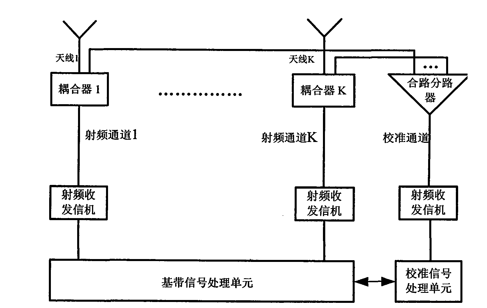
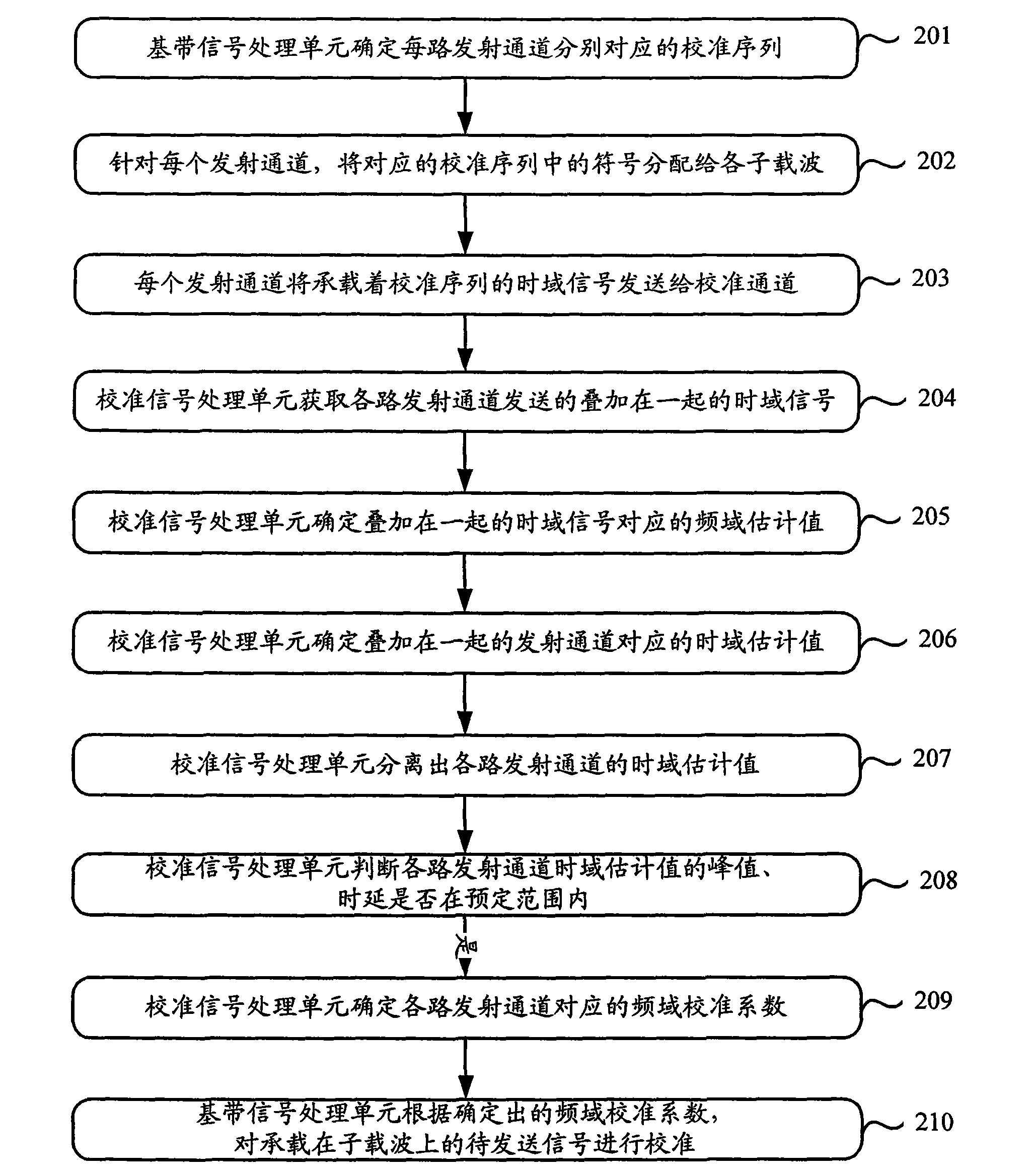
[0063] Please refer to the attached figure 2 , is a flow chart of calibrating transmission channels in this embodiment. In this embodiment, the smart antenna has k transmission channels in total.

[0064] Step 201, the baseband signal processing unit determines the calibration sequence corresponding to each transmission channel, the calibration sequence corresponding to each transmission channel should have good frequency domain autocorrelation and time domain autocorrelation, the calibration sequence corresponding to each transmission channel are orthogonal between them. For example, when selecting the ZC sequence as the calibration root sequence to determine the calibration sequences corresponding to the k transmission channels, the ZC sequence is used as the calibration sequence corresponding to the first transmission channel, and the other k-1 transmission channels are obtained through the cyclic shift method. the calibration sequence;

[0065] Step 202, for each transm...

Embodiment 2

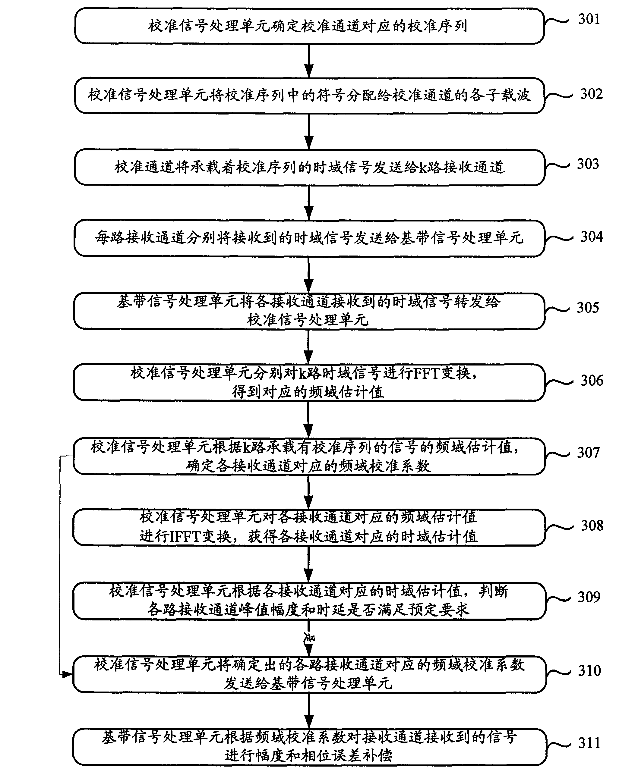
[0127] Please refer to the attached image 3 , is a flow chart of calibration processing for receiving channels in this embodiment. In this embodiment, the smart antenna has k transmission channels in total.

[0128] Step 301, the calibration signal processing unit determines the calibration sequence corresponding to the calibration channel;

[0129] Step 302, the calibration signal processing unit allocates the symbols in the calibration sequence corresponding to the calibration channel to each subcarrier of the calibration channel. For the specific allocation, please refer to the corresponding relationship between the symbols in the calibration sequence and each subcarrier in Embodiment 1. description, no more details here;

[0130] Step 303, the calibration channel passes the time-domain signal x carrying the calibration sequence through the combiner and splitter k (m) Send to k-way receiving channels, where

[0131] x k ( ...


PUM


Abstract

The invention discloses an intelligent calibration method of an antenna transmitting channel and an antenna receiving channel and a relevant device, which is used for solving the problem that signals transmitted in an LTE (Long Term Evolution) system can not be calibrated accurately by the traditional antenna calibration technology. The method comprises the following steps of: determining frequency domain calibration factors corresponding to subcarriers loading signals to be sent, exchanging the time domain estimation value of each transmitting channel, which is isolated from the time domain signal received by the calibration channel, to obtain the frequency domain estimation value of each subcarrier of each transmitting channel by the frequency domain calibration factors, and determiningthe frequency domain calibration factors corresponding to the subcarriers according to the frequency domain estimation value of each subcarrier; and when sending signals, calibrating the signals to be sent according to the determined frequency domain calibration factors corresponding to the subcarriers.

Description

technical field [0001] The present invention relates to the technical field of mobile communication, in particular to a method for determining the frequency domain calibration coefficient of a smart antenna transmission channel, a calibration method for a smart antenna transmission channel, a method for determining a frequency domain calibration coefficient for a smart antenna reception channel, a A method for calibrating a receiving channel of a smart antenna, a device for calibrating a transmitting channel of a smart antenna, and a device for calibrating a receiving channel of a smart antenna. Background technique [0002] attached figure 1 It is a structural schematic diagram of a smart antenna array system in an existing TD-SCDMA network, which includes a baseband signal processing unit, at least one antenna, at least one radio frequency transceiver, at least one coupler, combiner and splitter, and calibration signal processing unit. Usually, when transmitting a signal...

Claims


Application Information

Patent Timeline
IPC IPC(8): H04L27/26H04L25/03
Inventor 蒋峥张健飞孙长果于洋
Owner DATANG MOBILE COMM EQUIP CO LTD
Why Eureka
Try Eureka