Wave power plant and transmission

A technology for power generation equipment and equipment, which is applied in electromechanical devices, mechanical equipment, ocean energy power generation, etc., and can solve problems such as complex transmission systems and complex systems with large transmission losses

Inactive Publication Date: 2011-04-13
OCEAN HARVESTING TECH
View PDF12 Cites 17 Cited by
  • Summary
  • Abstract
  • Description
  • Claims
  • Application Information

AI Technical Summary

Problems solved by technology

Also, transmission systems have become more complex and hydraulics are often used in such systems
However, hydraulic equipment results in a complex system with large transmission losses

Method used


Image

  • Wave power plant and transmission
  • Wave power plant and transmission
  • Wave power plant and transmission

Examples


Embodiment Construction

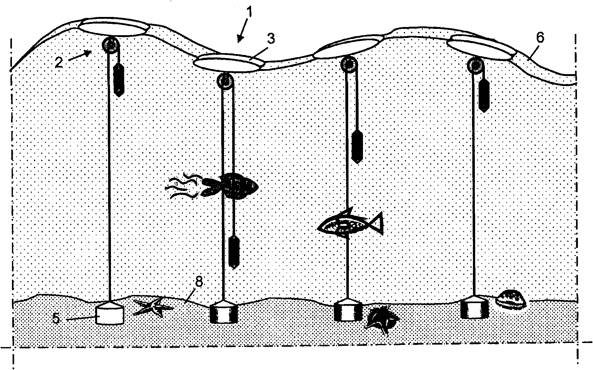
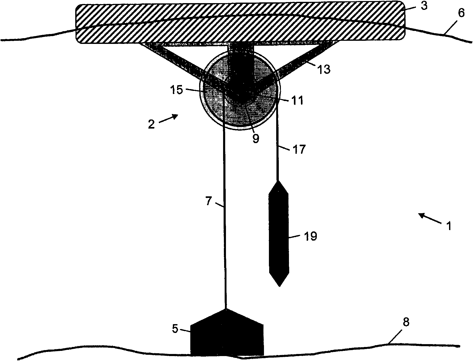
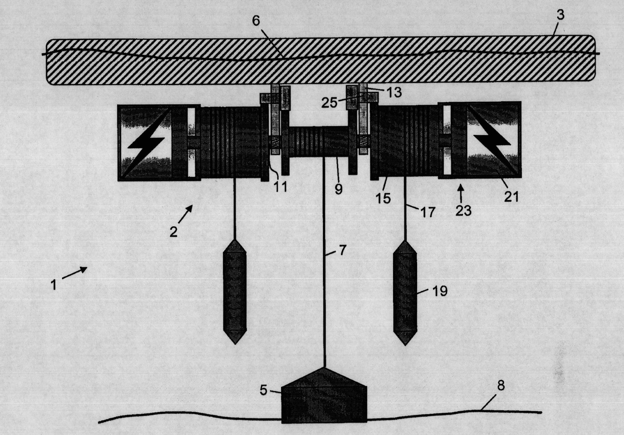
[0123] exist figure 1 In , a wave power plant is shown that extracts energy from the motion of waves on the water surface 6 of a pool, such as the motion of water in the ocean. The wave power generation facility comprises one or more wave power generation devices 1, each wave power generation facility 1 comprising a buoy or buoy 3 located on the water surface, for example floating on the water surface, and follows the movement of the waves to a greater or lesser degree. During the up and down movement of the water surface 6, the floats are alternately raised or lowered and / or alternately tilted back and forth. Thereby, a motive force can be generated, shown in this case with respect to the bottom 8 of the pool, for example a part rigidly attached to the bottom, such as the bottom base 5, which has a large enough to hold it stably on the bottom. quality. The bottom base can of course be attached to the bottom in some way if desired, and may include simple fastening means of l...


PUM


Abstract

A wave power generating equipment (1) includes a buoy (3) and a power train (2). In the transmission unit there is a driveshaft (11), which is driven to rotate either when the buoy rises or sinks, yet always in the same direction. The driveshaft is mechanically coupled to one of the rotating parts (21') of an electric generator (21) and drives this to generate electric current. Further on there is provided an energy accumulation device (105), which is also coupled to the driveshaft to accumulate energy when the buoy rises or sinks and the driveshaft rotates and which is then used to drive the generator at the other of the rising- and sinking motions. The coupling between the energy accumulation device and the driveshaft can go by the generator's second rotatable part (21'), the air gap between the generator's parts and the generator's first part. The coupling over the air gap gives a torque, which drives the second part to rotate along and which also counteracts the rotation of the driveshaft. The generator's second part is driven by the energy accumulation device to rotate in the other direction, when the torque from the driveshaft does not exceed the counteracting torque.

Description

[0001] related application [0002] This application claims the benefit of Swedish Patent Application No. 0800395-6, filed February 20, 2008, and Swedish Patent Application No. 0802165-1, filed October 10, 2008, the entire teachings of which are incorporated herein by reference. technical field [0003] The present invention relates to a wave power plant for extracting electrical energy from the motion of water waves, to a method of extracting electrical energy from substantially intermittent mechanical energy, such as the generally periodic motion of an object, and to a Drives for generating equipment used when permanent mechanical energy is available. Background technique [0004] Since the energy density in ocean waves is very high (about 1000 times higher than in wind), wave power generation has great potential in cost-benefit, so small-capacity wave energy converters become possible. Also, because waves are generated by the wind over long periods of time and continue t...

Claims


Application Information

Patent Timeline
Patent Type & Authority Applications(China)
IPC IPC(8): F03B13/18H02K23/60
CPCY02E10/38F05B2210/18F03B13/1815F05B2240/40Y02E10/30F03B13/14F03B13/16F03B13/18H02K23/60
Inventor M·西登马克
Owner OCEAN HARVESTING TECH
Why Eureka
Try Eureka