Injector for textile processing machine

A technology for processing machinery and ejectors, applied in the directions of jetting device, jetting device, textile and papermaking, etc., can solve the problems of impossible to manufacture fleece fabric materials, different densities of messy non-woven fibers, etc., to avoid differences and reduce wall thickness. The effect of part thickness

Inactive Publication Date: 2011-04-20
GROZ BECKERT KG
View PDF6 Cites 14 Cited by
  • Summary
  • Abstract
  • Description
  • Claims
  • Application Information

AI Technical Summary

Problems solved by technology

These differences between water jets lead to different densities of messy nonwoven fibers, making it impossible to fabricate fleece materials that exhibit uniform strength and density

Method used


Image

  • Injector for textile processing machine
  • Injector for textile processing machine
  • Injector for textile processing machine

Examples


Embodiment Construction

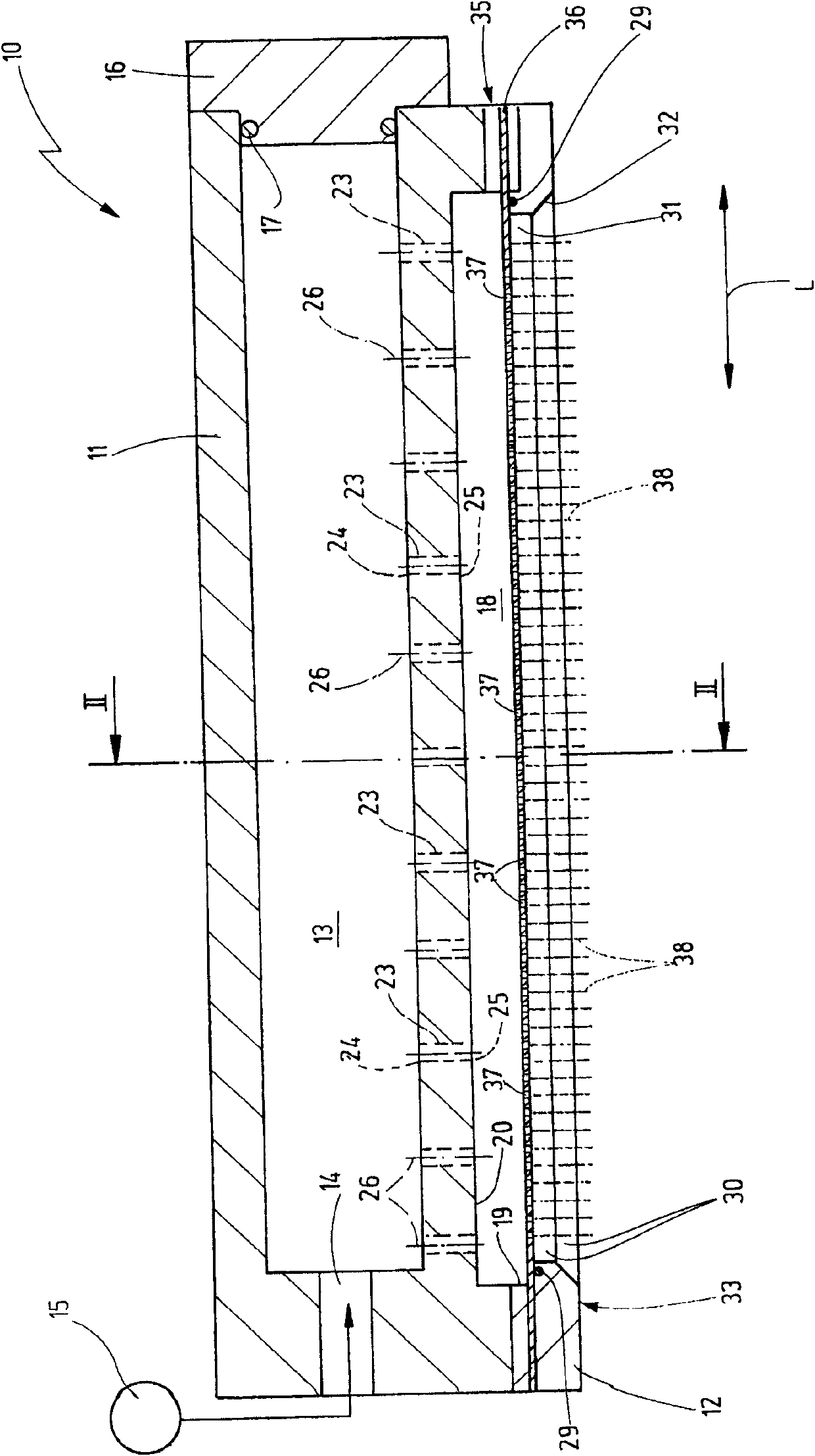
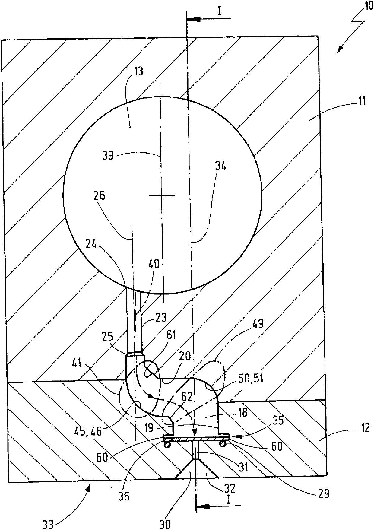
[0065] figure 1 A first exemplary embodiment of an injector 10 of a textile processing machine for producing pile fabric material is shown. The injector 10 includes an injector body 11 and an injector base 12 connected to each other. Inside the injector body 11 is an inflow chamber 13 which communicates with a pressure source 15 via an inflow opening 14 . In this exemplary embodiment, the inflow chamber 13 has a cylindrical shape. The inflow opening 14 is an aperture provided coaxially with respect to the longitudinal axis of the inflow chamber 13 . On the longitudinal end side opposite the inflow opening 14 , the inflow chamber 13 is closed in a fluid-tight manner by a screw-in cover 16 of the injector body 11 . To this end, an annular seal 17 may be provided between the cover 16 and the cover seat.

[0066] Furthermore, the injector 10 comprises a pressure distribution chamber 18 which extends in the longitudinal direction L in the region between the injector body 11 and...


PUM


Abstract

The invention relates to an injector for a textile processing machine, particularly to an injector for a textile processing machine for making napping textile materials. An inflow chamber is arranged in an injector main body for acquiring a pressing medium from the inflow chamber, wherein the inflow chamber is connected to the fluid in a pressure distribution chamber through a plurality of connecting pipes; a cylindrical opening arranged in the injector main body represents a connecting channel; the channels are arranged in one or two rows so as to shift away from a longitudinal central plane of the inflow chamber; the pressure distribution chamber adjoined with the connecting pipe comprises a first wall section for forming a first declination surface; the declination surface is at least diagonally or transversely extended relative to a longitudinal axis of the connecting pipes in a plurality of sections; the medium flowed from the connecting pipe declines through the first declination surface; a water injected flow is formed through a nozzle opening; and the water injected flow is injected by an outflow opening through the injector.

Description

technical field [0001] The invention relates to an injector for a textile processing machine. The injector includes an inflow chamber in fluid communication with, or in fluid communication with, a pressure source. The pressurized fluid or gaseous medium, preferably water, flowing into the chamber is also conveyed into the pressure distribution chamber via at least one communication channel, in particular via a plurality of communication channels. The pressure distribution chamber is in fluid communication with the outflow opening. For nozzle strips, there is a receiver for the strip-shaped nozzle foil between the pressure distribution chamber and the outflow opening. The nozzle foil has a plurality of nozzle openings providing fluid communication between the pressure distribution chamber and the outflow opening with the nozzle foil mounted in the receptacle. The nozzle opening is arranged to form a fine, needle-shaped medium jet, whereby said jet can be ejected by the injec...

Claims


Application Information

Patent Timeline
Patent Type & Authority Applications(China)
IPC IPC(8): D04H11/08D04H1/492
CPCD04H18/04D04H1/492B05B1/20
Inventor M·雷德勒
Owner GROZ BECKERT KG
Why Eureka
Try Eureka