External-mix self-priming pump

A self-priming pump and pump body technology, applied in the field of externally mixed self-priming pumps, can solve the problems of small contact area between blades and liquid, slow water filling speed, and long gas discharge time, so as to shorten water filling time and speed up gas-liquid The effect of short separation and discharge time

Inactive Publication Date: 2011-04-20
山东壮发泵业股份有限公司
View PDF0 Cites 0 Cited by
  • Summary
  • Abstract
  • Description
  • Claims
  • Application Information

AI Technical Summary

Problems solved by technology

[0003] The technical problem solved by the invention is to solve the problems of small contact area between the blade and the liquid, poor agitation in the pump body, poor gas-liquid mixing, long gas discharge time and slow water filling speed when the pump is initially working, and provides a blade and liquid External mixing self-priming pump with large contact area, strong agitation in the pump body, good gas-liquid mixing, short gas discharge time and fast water supply when the pump is initially working

Method used


Image

  • External-mix self-priming pump
  • External-mix self-priming pump
  • External-mix self-priming pump

Examples


Embodiment 1

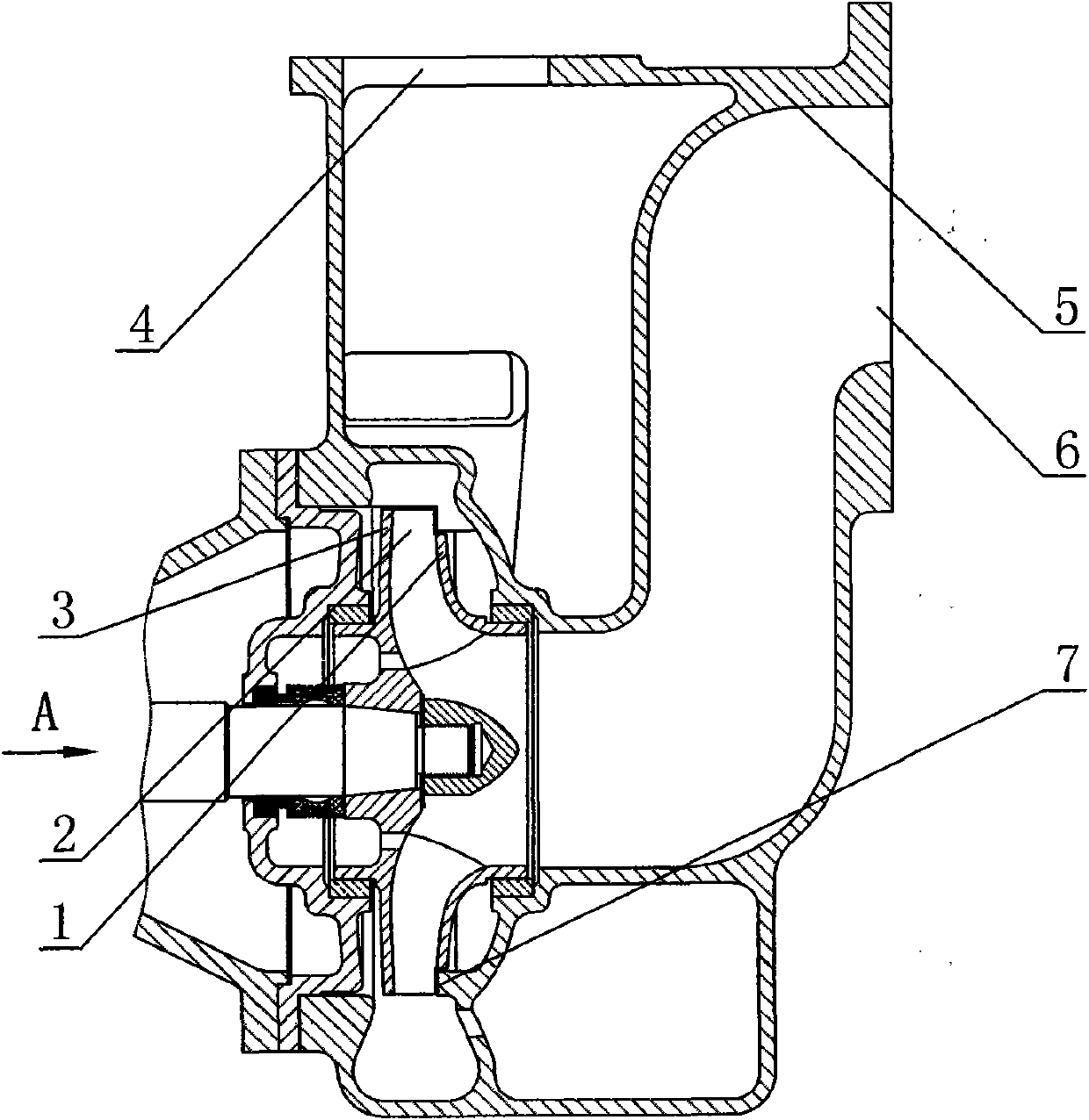
[0013] Such as figure 1 , figure 2 In the external mixing self-priming pump shown, one side of the pump body 5 is provided with a liquid inlet 6, the top of the pump body 5 is provided with a liquid outlet 4, the pump body 5 is provided with an impeller, and the impeller is provided with a front cover plate 1 and Back cover 3, vane 2 is arranged between front cover 1 and back cover 3, and the outer diameter of cover is provided with annular cutting band, from figure 1 It can be seen from the figure that there is an annular cutting zone on the outer diameter of the front cover plate 1, the blade at the annular cutting zone is not covered by the cover plate, the blade 2 is exposed, and the contact area between the blade 2 and the liquid is large. When the pump is initially working, the agitation in the pump body is strong , the gas-liquid mixing is good, the gas discharge time is short, and the water filling speed is fast. The inside of the pump body 5 is evenly distributed w...

Embodiment 2

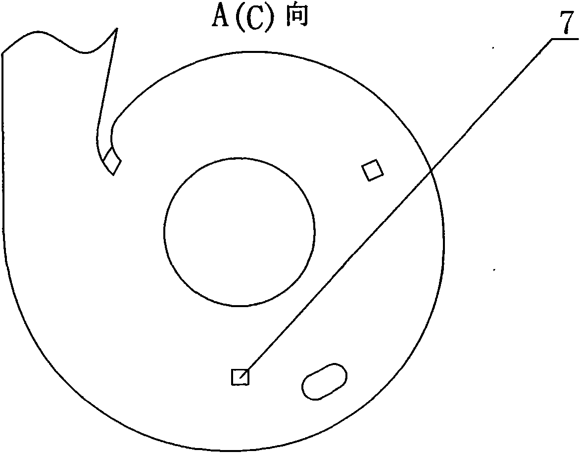
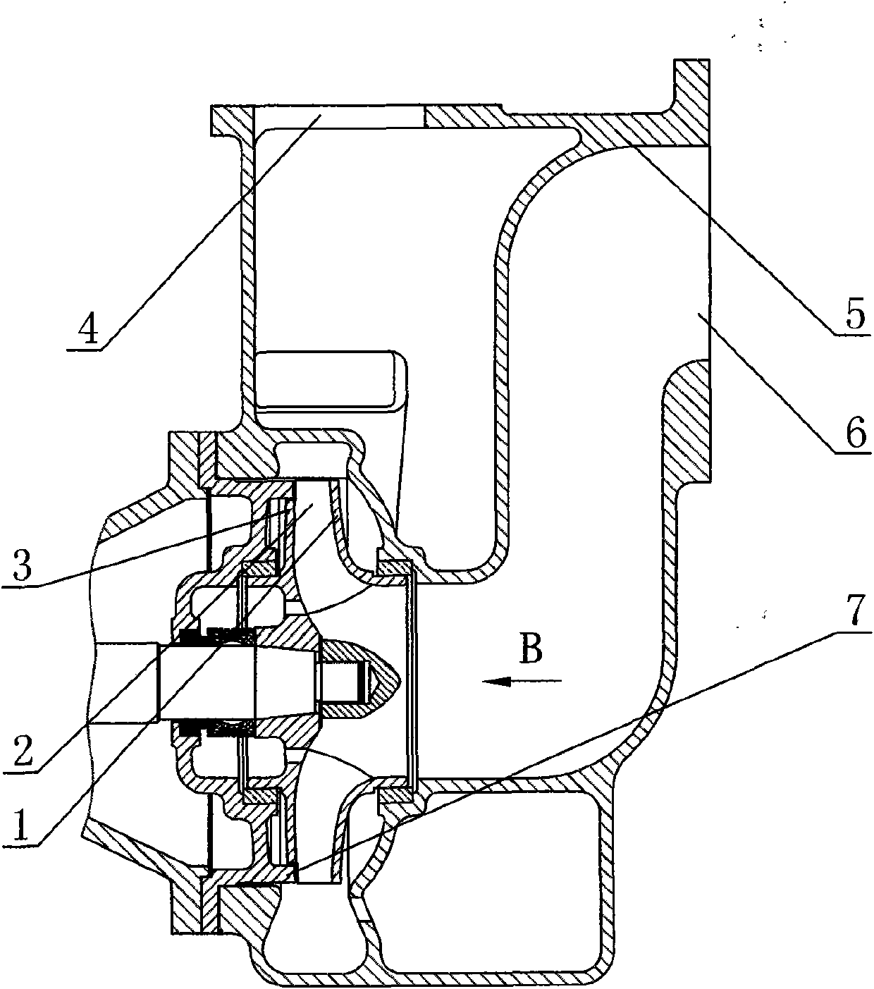
[0015] Such as image 3 , Figure 4 For the external mixing self-priming pump shown, there is an annular cutting zone on the outer diameter of the cover plate, from image 3 It can be seen that the outer diameter of the rear cover plate 3 is provided with an annular cut-off zone, and the inner part of the pump body 5 is evenly distributed with the boss 7 corresponding to the annular cut-off zone. Other structures are the same as those in Embodiment 1, and will not be repeated here.

Embodiment 3

[0017] Such as Figure 5 , figure 2 , Figure 4 For the external mixing self-priming pump shown, there is an annular cutting zone on the outer diameter of the cover plate, from Figure 5 It can be seen from the figure that the outer diameters of the front cover 1 and the rear cover 3 are respectively provided with annular cut-out bands, and the inside of the pump body 5 is evenly distributed with bosses 7 corresponding to the ring-shaped cut-out bands. Other structures are the same as those in Embodiment 1, and will not be repeated here.


PUM


Abstract

The invention discloses an external-mix self-priming pump and relates to pumps. A liquid inlet is formed on one side of a pump body; a liquid outlet is formed on the upper part of the pump body; an impeller is arranged inside the pump body; a front cover plate and a rear cover plate are arranged on the impeller; blades are arranged between the front cover plate and the rear cover plate; an annular cutting belt is arranged on external diameters of the cover plates; and lug bosses corresponding to the annular cutting belt are uniformly distributed inside the pump body. Because the annular cutting belt is arranged on the external diameters of the cover plates, the blades at the annular cutting belt are not covered by the cover plates and are exposed, the contact area of the blades and the liquid is large; when the pump starts to work, the agitation in the pump body is strong, the gas and the liquid is well mixed, the gas exhaust time is short and the water supply speed is high; and the lug bosses corresponding to the annular cutting belt are uniformly distributed inside the pump body, and when the pump works, the lug bosses are matched with the exposed blades; therefore, the gas-liquid mixtures are effectively scraped out, gas-liquid separation is accelerated, the water supply time is shortened, and the invention is applied to the external-mix self-priming pump.

Description

technical field [0001] The invention relates to pumps, in particular to an external mixing self-priming pump. Background technique [0002] We know that the existing external mixing self-priming pump is provided with a liquid inlet on one side of the pump body, a liquid outlet on the top of the pump body, an impeller in the pump body, a front cover and a rear cover on the impeller. plate, a blade is arranged between the front cover and the rear cover, and the diameters of the front cover, the rear cover and the blade are the same. This kind of external mixing self-priming pump, because the diameter of the front cover, the rear cover and the blade is the same, the contact area between the blade and the liquid is small, when the pump is initially working, the agitation in the pump body is poor, the gas-liquid mixing is poor, and the gas discharge time is long , The water speed is slow. Contents of the invention [0003] The technical problem solved by the invention is to s...

Claims


Application Information

Patent Timeline
Patent Type & Authority Applications(China)
IPC IPC(8): F04D9/02F04D29/22
Inventor 崔军波
Owner 山东壮发泵业股份有限公司
Why Eureka
Try Eureka