Method and device for achieving positioning and shearing control of flying shear by process software

A technology of software implementation and cutting edge position, which is applied in the direction of automatic control device, feeding device, digital control, etc., can solve the problems of complex control system, high quality requirements of engineering personnel and maintenance personnel, and high control cost

Active Publication Date: 2011-04-20
MCC HUATIAN NANJING AUTOMATION ENG
View PDF5 Cites 25 Cited by
  • Summary
  • Abstract
  • Description
  • Claims
  • Application Information

AI Technical Summary

Problems solved by technology

[0004] (1) The control system is complex, with many sources of interference and poor stability
Since the FM354 output signal can only be a positive or negative 10V analog quantity, its signal is given as the speed of the transmission device. If the PLC and the transmission device are not in the same place, the transmission of the signal is easily disturbed; at the same time, 0V zero drift also affects the stability of the system; FM354 must also accept on-site scissors coding signal, no matter what kind of communication method is used for transmission, if the signal is affected, it will directly affect the system stability
[0005](2) High cost of control
[0007](3) The control system is complex and requires high quality engineers and maintenance personnel
Regardless of the method (1) or (2), due to the existence of T400, the complex peripheral structure of the flying shear control system is fixed: the signal acquisition of the speed encoder of the final rolling mill or the front pinch roll, the signal acquisition of the position encoder of the shear blade, the hot and cold metal detector Signal acquisition, etc.; use S7-CFC programming to develop the corresponding function software of flying shears or set the T400 function parameters and process parameters are very complicated, requiring high quality engineering personnel and maintenance personnel
[0008](4) High cost of control

Method used


Image

  • Method and device for achieving positioning and shearing control of flying shear by process software
  • Method and device for achieving positioning and shearing control of flying shear by process software
  • Method and device for achieving positioning and shearing control of flying shear by process software

Examples


Embodiment Construction

[0033] The present invention will be described in further detail below in conjunction with the accompanying drawings and embodiments.

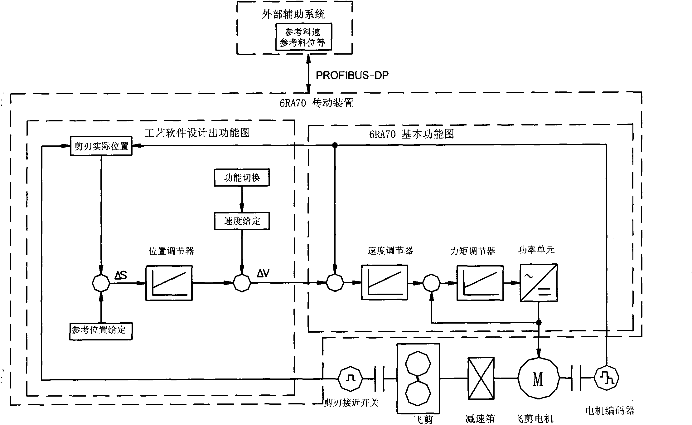
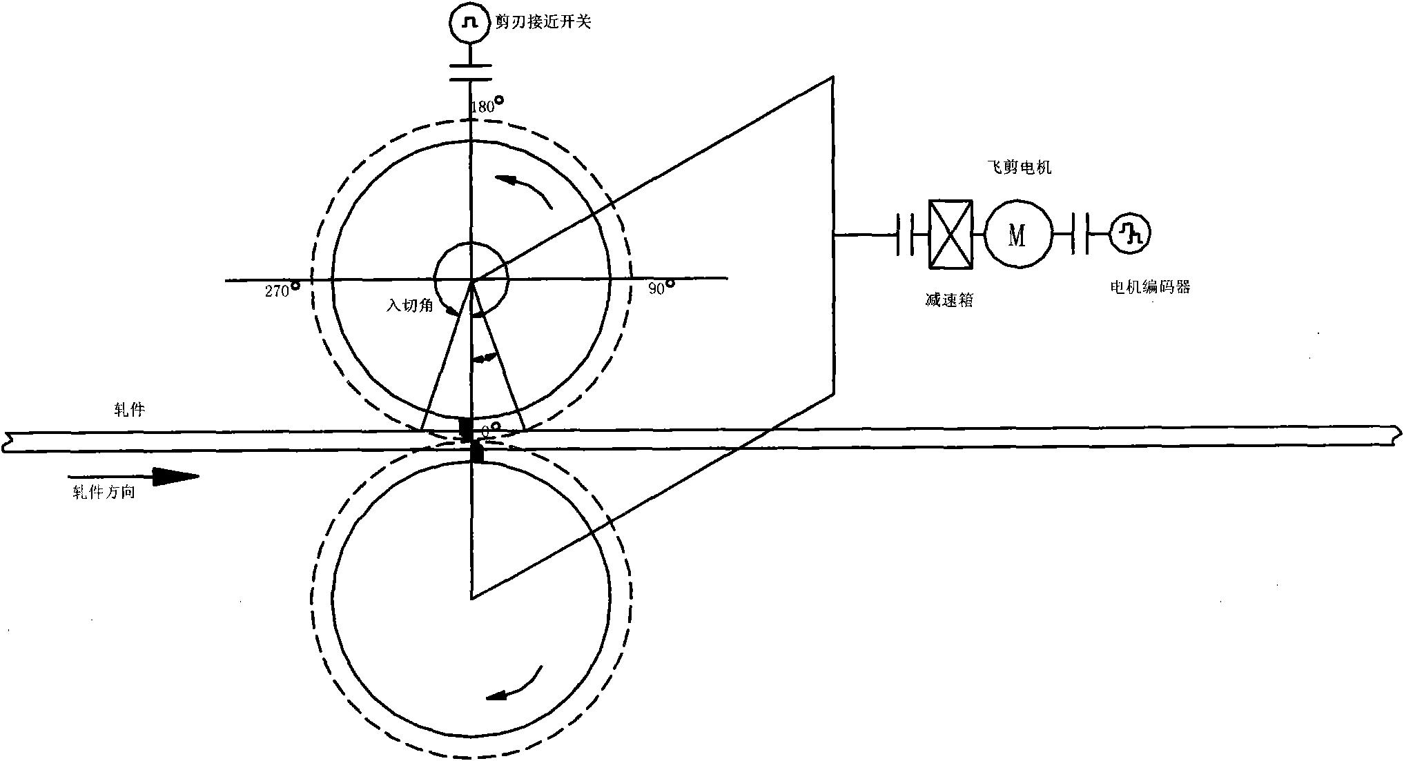
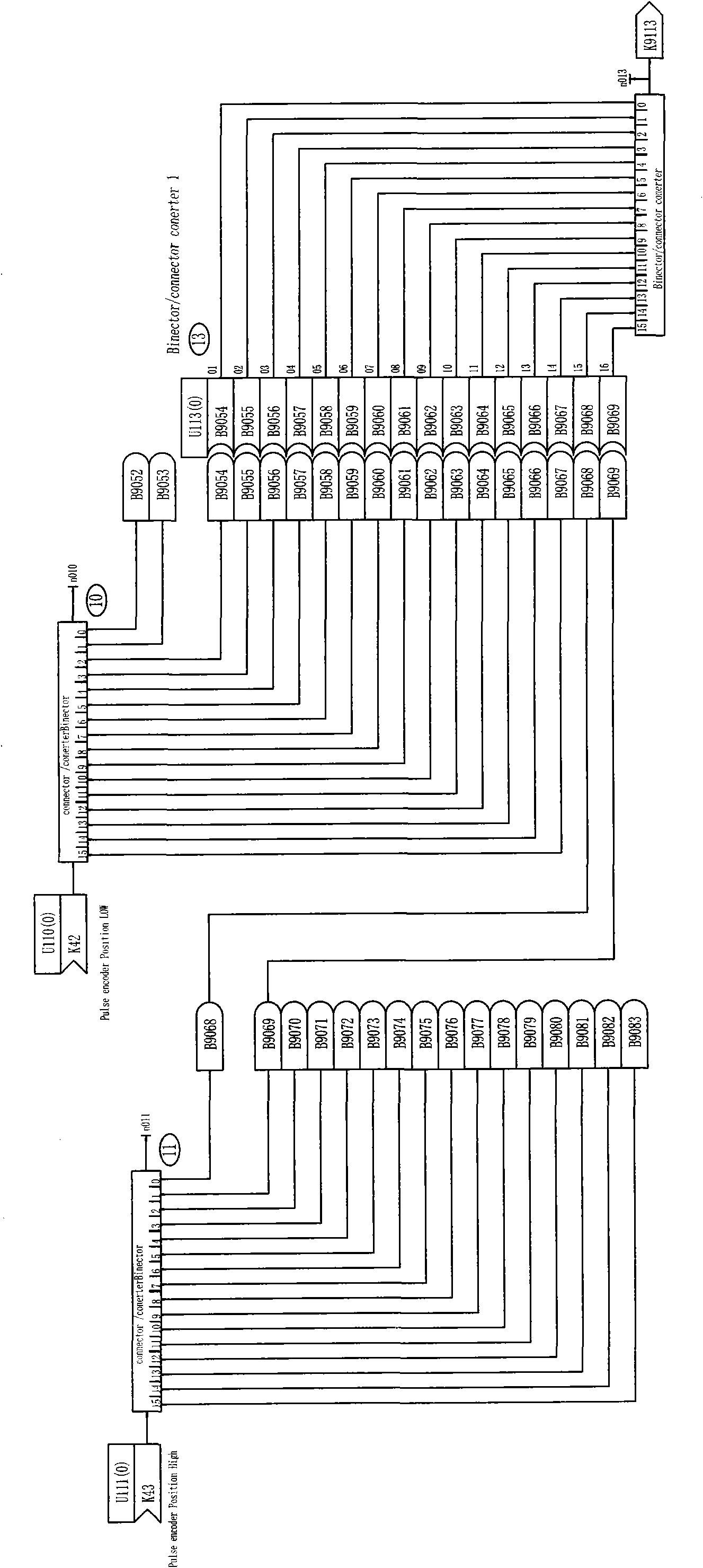
[0034] Such as Figure 1-7 As shown, the present invention only utilizes the built-in process software or programmable block in the transmission device of the flying shear motor to complete the precise positioning and cutting control of the flying shear. At present, the transmission device of flying shear basically has process software or programmable blocks. For example: SIEMENS DC device 6RA70 has process software S00, SIEMENS AC drive device 6SE70 has free free function blocks, ABB AC ACS800 and DC DCS800 devices have self-defined programming functions. Most of the driving motors for start-stop flying shears on the rolling line are DC motors, and most of the transmission devices are: SIEMENS SIMOREG DC-MASTER 6RA70. Taking the SIEMENS 6RA70 transmission device driving the flying shear DC motor as an example, the main technical solution of...


PUM


Abstract

The invention discloses a method and device for achieving the positioning and shearing control of a flying shear by process software, solving the problem of high cost, unstable signal and the like in the prior art. In the invention, a speed presetting module, a position presetting module and a function switch module are self-defined in the process software or a programmable block carried in a transmission device; an approach switch is arranged at the clipped corner position of a flying shear; the function switch module completes the switch control between the speed presetting module and the position presetting module through receiving the shear command of an external system and a signal sent by the approach switch; and the correct control of the positioning and shearing of the flying shear can be completed by controlling inside the transmission device. The method and the structure greatly reduce control hardware, bear low interference degree of the external signal, save the cost, are simple in operation, and have low requirement on an operator.

Description

technical field [0001] The invention relates to the field of rod and wire steel rolling, in particular to a method and device for realizing the positioning and shearing control of flying shears by using process software in the field of start-stop flying shear transmission and automatic control. Background technique [0002] Flying shear is one of the important equipment in the bar and wire rolling system, its working stability and reliability directly affect the product yield and production output. Start-stop flying shear positioning and cutting control are important links in flying shear control. At present, there are two types of control methods for realizing this control: 1. It is completed by PLC; 2. It is completed by the process board T400 (T400 is Siemens' transmission Such as 6RA70, 6SE70, etc.) configuration standard option). [0003] The positioning control of flying shears through PLC inevitably has the following problems: Take Siemens S300 CUP (6ES7 315-2AG10-0A...

Claims


Application Information

Patent Timeline
Patent Type & Authority Applications(China)
IPC IPC(8): G05B19/19B23Q15/00
Inventor 吴江
Owner MCC HUATIAN NANJING AUTOMATION ENG
Why Eureka
Try Eureka