Check patentability & draft patents in minutes with Patsnap Eureka AI!

Computer system and monitoring device for same

A computer system and monitoring device technology, applied in the field of computer systems, can solve problems such as high manpower and transportation costs, low maintenance efficiency, and difficulty in clarifying fault responsibility, so as to improve maintenance efficiency, facilitate maintenance, and reduce the probability of human error Effect

Inactive Publication Date: 2011-04-20
ASUSTEK COMPUTER INC
View PDF0 Cites 12 Cited by
  • Summary
  • Abstract
  • Description
  • Claims
  • Application Information

AI Technical Summary

Problems solved by technology

However, if the computer system cannot normally enter the operating system due to unknown reasons, the maintenance personnel will have no way of knowing whether the software and hardware of the computer system have been changed before the failure occurs, and it will be more difficult to judge the cause of the failure, and It is not easy to clarify who is responsible for the fault
[0009] The above-mentioned traditional methods require professionals with relevant knowledge to operate in person to troubleshoot or perform routine updates to the computer system, which requires manufacturers to pay high manpower and transportation costs, and the maintenance efficiency is low

Method used


Image

  • Computer system and monitoring device for same
  • Computer system and monitoring device for same
  • Computer system and monitoring device for same

Examples


Embodiment Construction

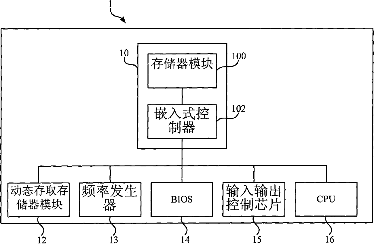
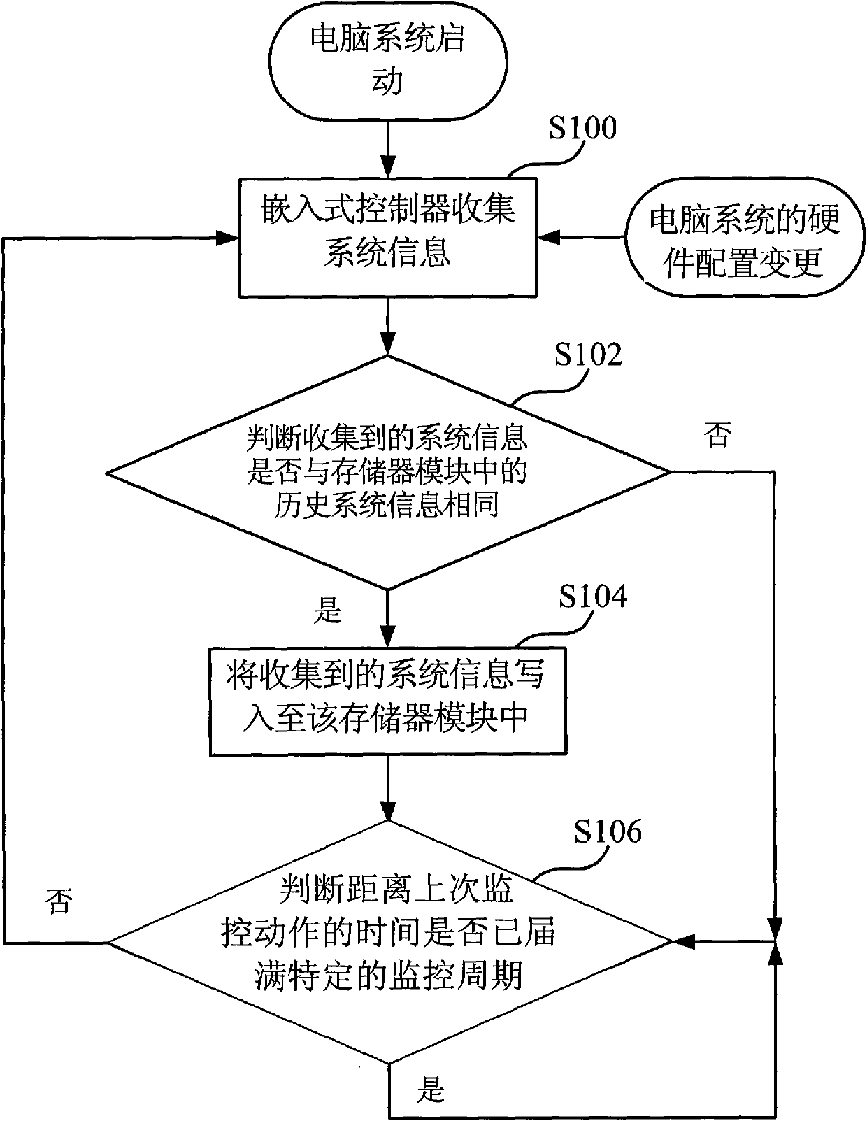
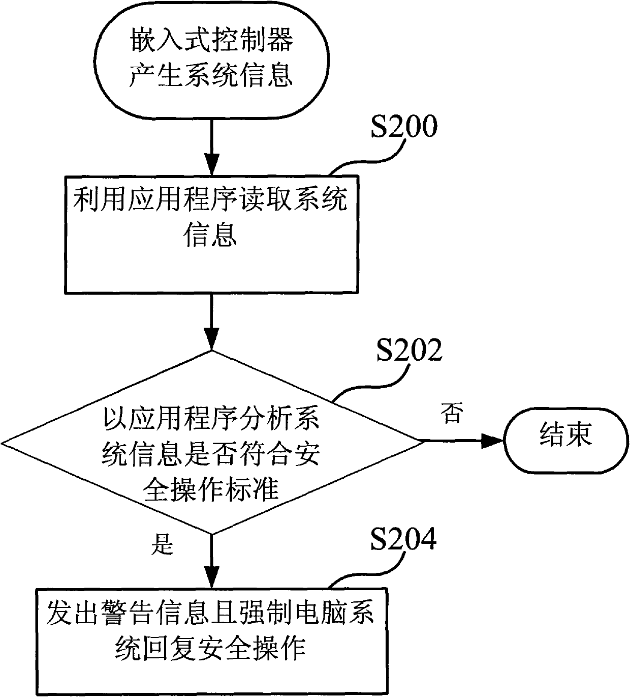
[0018] see figure 1 , figure 1 Shown is a functional block diagram of a computer system 1 according to an embodiment of the present invention. Such as figure 1 As shown, the computer system 1 includes a monitoring module 10 and a plurality of electronic modules. In this embodiment, the plurality of electronic modules can be respectively a dynamic access memory (Dynamic Random Access Memory, DRAM) module 12, a frequency generator 13, a basic Input and output system (Basic Input / Output System, BIOS) 14, input and output control chip 15 and central processing unit (Central Process Unit, CPU) 16 and other required circuit elements in various computer systems, but the present invention does not use this limit.

[0019] Such as figure 1 As shown, the monitoring module 10 includes a memory module 100 and an embedded controller 102 . In this embodiment, the memory module 100 can use a non-volatile memory (non-volatile memory) element that cannot be rewritten. The characteristic o...


PUM


Abstract

The invention discloses a computer system and a monitoring device for the same. The computer system comprises a plurality of electronic modules, a memory module and an embedded controller, wherein the embedded controller is coupled to the plurality of electronic modules and the memory module respectively; the embedded controller acquires the states of the plurality of electronic modules and generates system information related to the plurality of electronic modules; the embedded controller selectively writes the acquired system information into the memory module; the system information in the memory module can be provided for a user or a maintainer to analyze; and the computer system can monitor the system information by an application program, so that prevention and warning functions can be achieved.

Description

technical field [0001] The present invention relates to a computer system, and in particular to a monitoring device for monitoring and recording the system status of the computer system. Background technique [0002] At present, various computer systems have been widely used in various applications such as government agencies, commercial offices, families and even individuals to store or process many important information. With the prolongation of the working time of the system or the possible improper operation of the user, the computer system often produces various faults or maintenance requirements. [0003] Generally speaking, the computer system can usually eliminate or repair the fault situation through a certain process, and the manufacturer of the computer system also provides users with simple technical explanation documents or a dedicated service line for remote technical support. But after all, the current computer system already has a large number of software an...

Claims


Application Information

Patent Timeline
IPC IPC(8): G06F11/34G06F11/30
Inventor 吴瑮倩黄百庆
Owner ASUSTEK COMPUTER INC
Features
  • R&D
  • Intellectual Property
  • Life Sciences
  • Materials
  • Tech Scout
  • Unparalleled Data Quality
  • Higher Quality Content
  • 60% Fewer Hallucinations
Learn More