Coordination control method for crossroad left-turning pre-signal and straight-going successive signal

A technology for coordinated control of intersections, which is applied to control traffic signals and other directions, can solve problems such as left-turn traffic jams, frontal collisions, and no conflict points for left-turn vehicles, so as to eliminate conflicts, avoid congestion, and ensure driving safety. Effect

Inactive Publication Date: 2011-04-20
JIANGSU UNIV
View PDF9 Cites 49 Cited by
  • Summary
  • Abstract
  • Description
  • Claims
  • Application Information

AI Technical Summary

Problems solved by technology

However, this method has two major deficiencies: one is that it does not really eliminate the conflict point between the left-turn vehicle and the oncoming straight vehicle, but only shifts the conflict point to a road section far away from the intersection, and once the conflict occurs, it will be serious frontal collision
The second is that the method stipulates that during the period when the oncoming straight traffic on the same road section is a red light (during the green light period of the intersecting road), the left-turning vehicle is allowed to cross the center line of the road and the straight exit lane in advance, and enter the right-turn exit in the straight exit lane. The special left-turn entrance lane between the lanes, but if the left-turn traffic flow is too large, it is difficult to pass all the oncoming through traffic during the red light period, which will cause left-turn traffic jams

Method used


Image

  • Coordination control method for crossroad left-turning pre-signal and straight-going successive signal
  • Coordination control method for crossroad left-turning pre-signal and straight-going successive signal
  • Coordination control method for crossroad left-turning pre-signal and straight-going successive signal

Examples


Embodiment

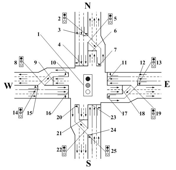
[0083] figure 1 See Table 1 for information such as the flow rate and saturated flow rate of the intersection shown, and the total loss time of timing is taken as 10 seconds.

[0084] Table 1 Arrival traffic and other information at the intersection of the example

[0085]

[0086] According to the formula ( e ), the key flow ratio of the north-south phase is calculated as follows:

[0087]

[0088] According to the formula ( f ), the critical flow ratio of the east-west phase is calculated as follows:

[0089]

[0090] According to the formula ( h ), the cycle duration can be obtained:

[0091]

[0092] According to the formula ( i ), the green light time of the north-south phase of the main signal is:

[0093]

[0094] According to the formula ( j ), the green light time of the east-west phase of the main signal is:

[0095]

[0096] According to the formula ( k ) ~ formula ( n ), the green light distribution of the left turn pre-signal is as fol...


PUM


Abstract

The invention discloses a coordination control method for a crossroad left-turning pre-signal and a straight-going successive signal, which comprises the steps that: a main signal lamp is arranged at first in the middle of a crossroad, left-turning pre-signal lamps are respectively arranged at first stop lines of four left-turning entrance lanes for left turning vehicles, straight-going successive signal lamps are respectively arranged in front of second stop lines of four exit lanes for straight-going vehicles; a main signal phase, a phase difference between the left-turning pre-signals and the straight-going successive signals, and a phase difference between the straight-going successive signals and the main signal are then configured, time allocation is prepared, the sum of key flow ratios of the phases is calculated, and the time for green light is finally allocated; according to the method disclosed by the invention, the contradiction in the aspect of time between the left-turning vehicles and the straight-going vehicles is thoroughly settled by means of the coordination control for the main signal, the pre-signals and the successive signals, thereby guaranteeing drive safety; the entire cycle for the coordination control only needs to be calculated once, which is fast and convenient, and the method effectively avoids that the adoption of traditional time allocation method is likely to lead to the jam of left-turning vehicles.

Description

technical field [0001] The invention belongs to the field of urban road traffic control, and relates to a method for controlling a pre-signal light of a left-turn motor vehicle at an intersection entrance and a follow-up signal light of a straight-going motor vehicle. Background technique [0002] At present, at intersections, two-phase signal control methods and multi-phase signal control methods are commonly used to control signal lights. The two-phase signal control method cannot avoid the conflict between left-turning traffic flow and oncoming through-going traffic flow. For example, the multi-phase signal control method of two-way left-turning four-phase signal control method can avoid the conflict between left-turning and straight-going traffic in time, but it will increase the cycle time and The timing loses time and increases the delay of traffic flow. Restricting left turns increases the detour distance for left-turning vehicles. Therefore, the management and cont...

Claims


Application Information

Patent Timeline
Patent Type & Authority Applications(China)
IPC IPC(8): G08G1/07G08G1/08
CPCG08G1/07
Inventor 张鹏常玉林李文权
Owner JIANGSU UNIV
Why Eureka
Try Eureka