Adjusting method for dynamic reactive compensation controller

A technology of compensation controller and adjustment method, applied in reactive power compensation, reactive power adjustment/elimination/compensation, AC network to reduce harmonics/ripple, etc. , It is difficult to take into account power factor and other issues to ensure safe and stable operation, improve power factor, and stabilize bus voltage.

Inactive Publication Date: 2013-09-25
GUANGDONG MINGYANG LONGYUAN POWER ELECTRONICS
View PDF3 Cites 1 Cited by
  • Summary
  • Abstract
  • Description
  • Claims
  • Application Information

AI Technical Summary

Problems solved by technology

However, due to the complexity of the system itself, it is often difficult to balance the above goals
Traditional SVC reactive power compensation devices often set control strategies according to specific requirements. When the control target is to maintain system voltage stability, it is difficult to take power factor into account. When the control target is to increase power factor and reduce reactive power, it is difficult to consider the busbar When the voltage is stable

Method used


Image

  • Adjusting method for dynamic reactive compensation controller
  • Adjusting method for dynamic reactive compensation controller
  • Adjusting method for dynamic reactive compensation controller

Examples


Embodiment Construction

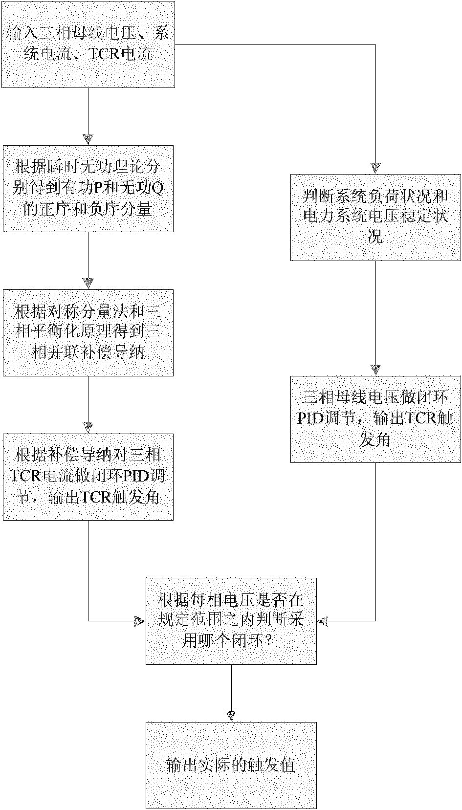
[0022] An adjustment method for a dynamic reactive power compensation controller, comprising the following steps:

[0023] The first step is to collect the bus current i of the three-phase system in real time a i b i c , three-phase system bus voltage u a , u b , u c , the current of the three-phase thyristor phase-controlled reactor (TCR current);

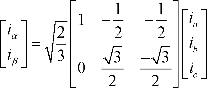
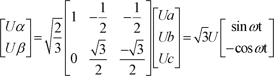
[0024] After the first step, the three-phase system current and three-phase system voltage on the a, b, and c coordinates are transformed into two-phase current and two-phase voltage on the α, β coordinates by 3 / 2 transformation:

[0025] i α i β = 2 3 1 - 1 ...


PUM


Abstract

The invention discloses an adjusting method for a dynamic reactive compensation controller. The adjusting method comprises the following steps: firstly, collecting the busbar current of a three-phase system, the busbar voltage of the three-phase system and the current of a three-phase thyristor controlled reactor in real time; then carrying out closed loop proportional-integral-differential (PID) adjustment on the current of the three-phase thyristor controlled reactor according to the compensated admittance of each parallel branch, and outputting the triggering angle of the thyristor controlled reactor; simultaneously, carrying out closed loop PID adjustment on the busbar voltage of the three-phase system, and outputting the triggering angle of the thyristor controlled reactor; and finally, according to whether each phase of voltage is in a specific range or not, judging whether to adopt the closed loop PID adjustment of the second step or the third step, and outputting the actual triggering angle of the thyristor controlled reactor. The method provided by the invention can increase the power factor, reduce the reactive power, decrease the line loss, improve the transmission capacity of the active power of a power transmission line, stabilize the busbar voltage, and inhibit the voltage fluctuation and flicker.

Description

[technical field] [0001] The invention relates to an adjustment method for a dynamic reactive power compensation controller. [Background technique] [0002] The control method of the static dynamic var compensator in the power system is the core technology of the static dynamic var compensation device, and it is also the key to the stable operation of the device. The role of the static dynamic reactive power compensation device in the power system is: [0003] 1. Filter out system harmonics, improve power factor, and suppress three-phase unbalance; [0004] 2. Maintain a stable voltage in a weaker power system; [0005] 3. Suppress voltage fluctuation and flicker caused by impulsive reactive load; [0006] 4. Improve the transient stability of the transmission system; [0007] 5. Improve the voltage stability of the power receiving system; [0008] 6. Suppress power oscillation; [0009] 7. Adjust the voltage of long-distance transmission lines to reduce transmission l...

Claims


Application Information

Patent Timeline
Patent Type & Authority Patents(China)
IPC IPC(8): H02J3/18H02J3/01
CPCY02E40/30Y02E40/40
Inventor 周立专周治国张佳丽
Owner GUANGDONG MINGYANG LONGYUAN POWER ELECTRONICS
Why Eureka
Try Eureka