Electric toothbrush

An electric toothbrush and vibrating body technology, applied in dentistry, prosthodontics, cleaning teeth, etc., can solve the problems of miniaturization of difficult-to-brush parts and complicated mechanism.

Active Publication Date: 2011-04-20
OMRON HEALTHCARE CO LTD
View PDF1 Cites 26 Cited by
  • Summary
  • Abstract
  • Description
  • Claims
  • Application Information

AI Technical Summary

Problems solved by technology

[0003] However, these technologies tend to complicate the mechanism for transmitting vibrations or make it difficult to miniaturize the vicinity of the bristles.

Method used


Image

  • Electric toothbrush
  • Electric toothbrush
  • Electric toothbrush

Examples


no. 1 example

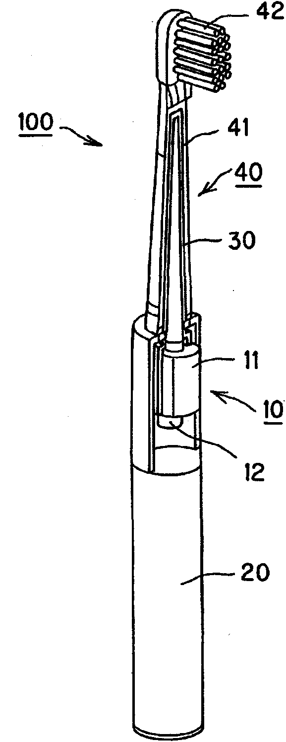
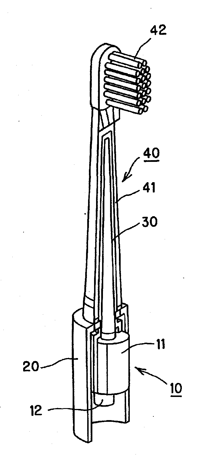
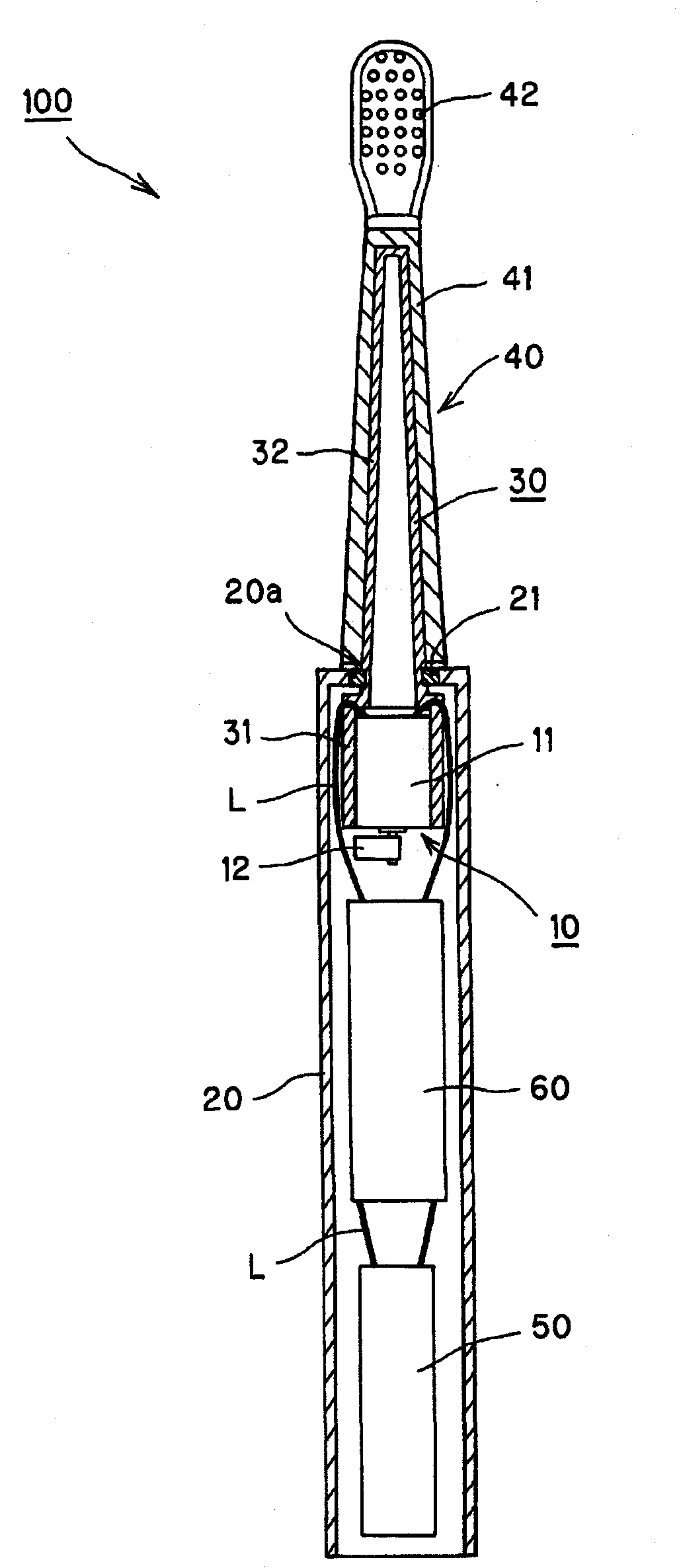
[0045] refer to Figure 1 to Figure 5 , an electric toothbrush according to a first embodiment of the present invention will be described. figure 1 It is a partially cutaway perspective view of the electric toothbrush according to the first embodiment of the present invention. figure 2 yes figure 1 A partial enlargement of the . image 3 It is an internal structural diagram of the electric toothbrush of the first embodiment of the present invention. Figure 4 It is a schematic cross-sectional view showing the main components of the electric toothbrush according to the first embodiment of the present invention. Figure 5 It is an explanatory diagram explaining the state of vibration transmission of the electric toothbrush according to the first embodiment of the present invention.

[0046]

[0047] especially with reference to Figure 1~4 , and the overall structure and the like of the electric toothbrush according to the first embodiment of the present invention will b...

no. 2 example

[0063] exist Image 6 with Figure 7 A second embodiment of the invention is shown in . In the above-mentioned first embodiment, the case where the counterweight is provided on the one end side of the motor is shown, but in this embodiment, the case where the counterweight is provided on the other end side of the motor is shown. The other structures and functions are the same as those of the first embodiment, so the same reference numerals are assigned to the same structural parts, and descriptions thereof are omitted.

[0064] Image 6 It is a partially cutaway perspective view of an electric toothbrush according to a second embodiment of the present invention. Figure 7 It is a schematic cross-sectional view showing main components of an electric toothbrush according to a second embodiment of the present invention.

[0065] In the electric toothbrush 100a of the present embodiment, the vibration source 10a includes: a motor 11a inserted into the cylindrical portion 31 of...

no. 3 example

[0068] exist Figure 8 with Figure 9 A third embodiment of the invention is shown in . In this embodiment, a structure in which a vibration attenuating body is added between the vibrating body and the annular member (a member functioning as a position restricting portion) in the structure of the first embodiment described above, the vibration attenuating body is used for The vibration of the vibrating body is suppressed from being transmitted to the case. The other structures and functions are the same as those of the first embodiment, so the same reference numerals are assigned to the same structural parts, and descriptions thereof are omitted.

[0069] Figure 8 with Figure 9 It is a schematic cross-sectional view showing main components of an electric toothbrush according to a third embodiment of the present invention.

[0070] As described in the first embodiment, the ring member 22 for restricting the movement of the vibrating body 30 to one end side is provided on...


PUM


Abstract

Disclosed is an electric toothbrush capable of applying large vibration to the brush by small vibrations of a vibration source. An electric toothbrush (100) is provided with a tubular casing (20) and a vibrating body (30) that applies vibration to a brush (42), one end of which is positioned in the interior of the casing (20), while the other end thereof is arranged so as to project to outside the casing from an aperture (20a) at the tip of the casing, the brush (42) being positioned in the vicinity of this other end. A vibration source (10) is arranged at one end of the vibrating body (30), and the outer peripheral surface of the vibrating body (30) is supported in a position that is more offset towards the vibration source (10) than the centre of this vibrating body (30) in the longitudinal direction thereof.

Description

technical field [0001] The present invention relates to electric toothbrushes. Background technique [0002] Conventionally, an electric toothbrush is known in which a vibration source is provided inside a toothbrush main body to transmit vibration to bristles (see Patent Documents 1 and 2). In such an electric toothbrush, in order to efficiently vibrate the bristles, for example, a technique of improving vibration transmission efficiency or generating resonance is used. [0003] However, these techniques tend to complicate the mechanism for transmitting vibrations or make it difficult to downsize the vicinity of the bristle portion. Therefore, it is desirable to have a technology that makes the vibration of the vibration source small and vibrates the bristles greatly. [0004] Patent Document 1: JP Utility Model Registration No. 3008856 Gazette; [0005] Patent Document 2: JP-A-10-192054. Contents of the invention [0006] The problem to be solved by the invention ...

Claims


Application Information

Patent Timeline
Patent Type & Authority Applications(China)
IPC IPC(8): A61C17/22
CPCA61C17/3481A61C2204/002
Inventor 岩堀敏之三木章利
Owner OMRON HEALTHCARE CO LTD
Why Eureka
Try Eureka