Transport refrigeration system and method of operation

A refrigerant and compression system technology, applied in refrigerators, refrigeration components, transportation and packaging, etc., can solve problems such as low mass flow rate

Inactive Publication Date: 2011-04-20
CARRIER CORP
View PDF1 Cites 15 Cited by
  • Summary
  • Abstract
  • Description
  • Claims
  • Application Information

AI Technical Summary

Problems solved by technology

It results in very low mass flow rates under perishable part load operating conditions

Method used


Image

  • Transport refrigeration system and method of operation
  • Transport refrigeration system and method of operation
  • Transport refrigeration system and method of operation

Examples


Embodiment Construction

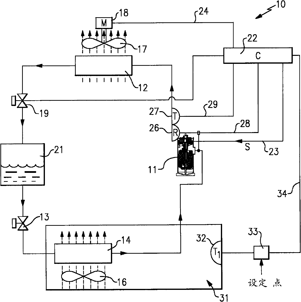
[0015] The present invention, shown generally at 10, is incorporated into a refrigerant vapor compression system utilizing CO 2 Operating as a refrigerant and comprising a compressor 11 , a refrigerant heat sink heat exchanger 12 , an expansion device 13 and a refrigerant heat sink heat exchanger 14 in series flow relationship. A refrigerant absorption heat exchanger 14, commonly referred to as an evaporator, includes a motor driven fan 16 for circulating air thereover for cooling.

[0016] Since the system uses CO 2 As a working fluid, it must operate in a transcritical cycle such that the high-pressure refrigerant of the refrigerant-radiation heat exchanger 12 (which may be referred to as a condenser) is in contact with the cooling medium (most commonly ambient) in an air conditioning system or transport refrigeration system. Air) is transferred in a heat exchange relationship. In such a refrigerant vapor compression system operating in a transcritical cycle, the refrigera...


PUM


Abstract

A refrigerant vapor compression system using CO2 as the working fluid and operating in a transcritical cycle, compression of the refrigerant is accomplished by use of a digital scroll compressor adapted to a variable duty cycle in a pulse width modulation manner. The compression ratio is maintained at an acceptable level by selective control of various components within the system, depending on the mode of operation.

Description

technical field [0001] The present invention relates generally to transport refrigeration systems, and more particularly to capacity modulation of refrigerant vapor compression systems operating in transcritical cycles. Background technique [0002] Refrigerant vapor compression systems are well known in the art and are commonly used to condition the air supplied to a climate-controlled comfort zone within a residence, office building, hospital, school, restaurant, or other facility. Refrigerant vapor compression systems are also commonly used in transport refrigeration systems to cool the air supplied to the temperature-controlled cargo space of a truck, trailer, container, or the like used to transport perishable items. Traditionally, most of these refrigerant vapor compression systems operate at subcritical refrigerant pressures and typically include a compressor, a condenser and evaporator, and an expansion device (usually an expansion valve) that Flow placement is upst...

Claims


Application Information

Patent Timeline
Patent Type & Authority Applications(China)
IPC IPC(8): F25B1/00F25B1/04F25B49/02F25B9/00
CPCF25B2700/21152Y02B30/743F25B2700/19F25B49/02F25B2341/0662F25B2600/111F25B49/022F25B2309/061F25B2600/025F25B2700/1931F25B2400/23F25B2400/13F25B2700/2104F25B9/008F25B49/027F25B2600/0251B60H1/3216B60H2001/3292F25B31/008F25B41/39
Inventor Y·H·陈L·Y·刘
Owner CARRIER CORP
Why Eureka
Try Eureka