Parallel type ankle rehabilitation training apparatus

An ankle joint and parallel technology, which is applied in the field of rehabilitation engineering, can solve problems such as difficulty in satisfying ankle joint rehabilitation training, misalignment between the rotation center and the ankle joint, difficult ankle joint rehabilitation training, etc., to achieve good rigidity, good dynamic performance, and load bearing The effect of high ability

Inactive Publication Date: 2012-10-03
SHANGHAI DIANJI UNIV
View PDF2 Cites 2 Cited by
  • Summary
  • Abstract
  • Description
  • Claims
  • Application Information

AI Technical Summary

Problems solved by technology

At present, the main structural form of the ankle joint rehabilitation training device is a single-degree-of-freedom rotating hinge, which only realizes the dorsiflexion / plantar flexion of the ankle joint, and it is difficult to meet the requirements of comprehensive ankle joint rehabilitation training.
After searching the existing relevant technical literature, it is found that the Chinese patent application number is: 200810034002.7, and the name is "parallel multi-freedom prosthetic exoskeleton ankle joint". Although the exoskeleton ankle joint adopts a multi-degree-of-freedom parallel mechanism, but -RPS type parallel mechanism can only realize rotation in two directions, and the rotation center is not fixed
The Chinese patent application number is: 200820073836.4, and the name is "an ankle joint rehabilitation robot". Although the ankle joint rehabilitation robot adopts a parallel mechanism with three rotational degrees of freedom, its fixed rotational center does not coincide with the ankle joint. Therefore, it is difficult to effectively realize the rehabilitation training of the ankle joint

Method used


Image

  • Parallel type ankle rehabilitation training apparatus
  • Parallel type ankle rehabilitation training apparatus
  • Parallel type ankle rehabilitation training apparatus

Examples


Embodiment Construction

[0010] The embodiments of the present invention will be described in detail below in conjunction with the accompanying drawings. This embodiment is implemented on the premise of the technical solution of the present invention, and detailed implementation methods and specific operating procedures are provided, but the scope of protection of the present invention is not limited to the following the described embodiment.

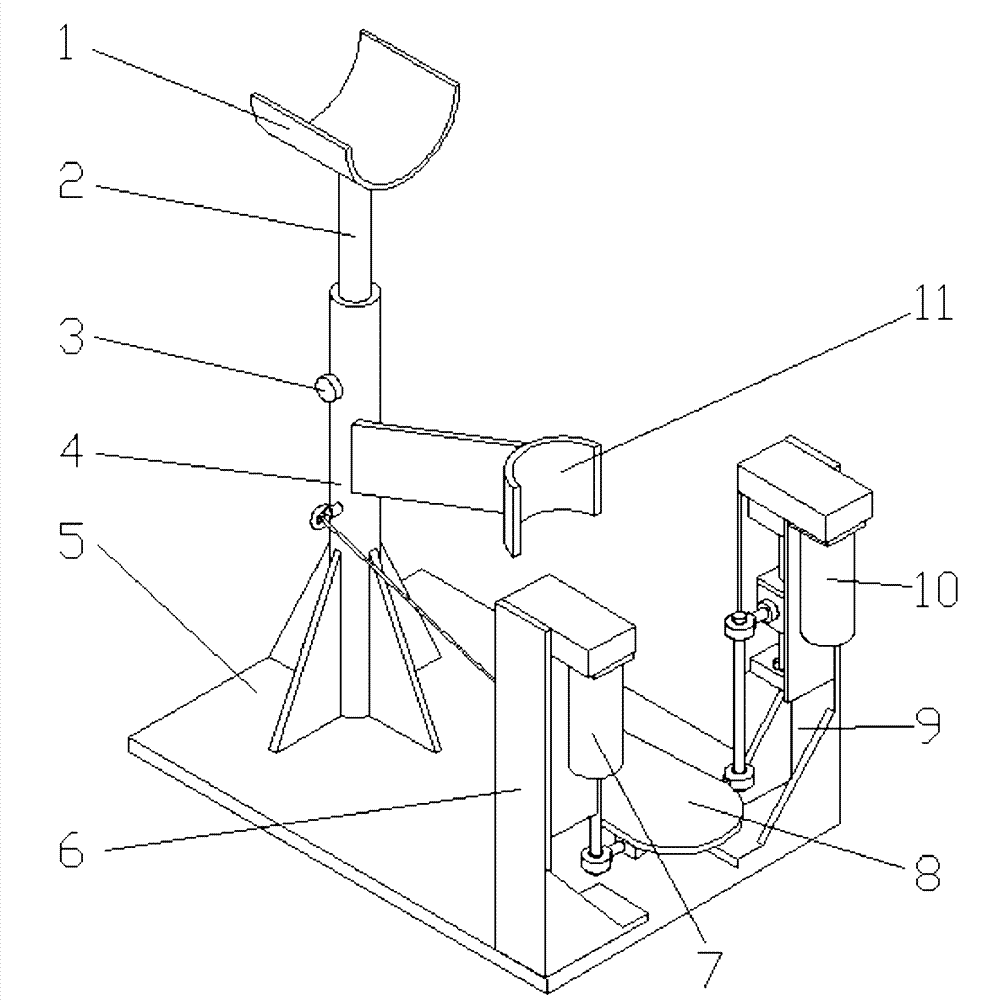
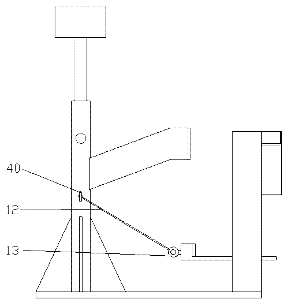
[0011] As shown in Figure 1, this embodiment includes: thigh support seat 1, thigh support seat inner rod 2, locking screw 3, thigh support seat outer rod 4, calf connection sleeve 11, sole support plate 8, first movement support Chain 10, second motion branch chain 7, first motion branch chain support frame 9, second motion branch chain support frame 6, base plate 5, fixed lug 40, plantar support plate lug 13, rope 12, wherein: thigh The outer rod 4 of the support seat is fixedly connected with the base plate 5; the thigh support seat 1 is fixedly connected wi...


PUM


Abstract

The invention relates to a parallel type ankle rehabilitation training apparatus. The parallel type ankle rehabilitation training apparatus comprises a thigh support base, a thigh support base internal rod, a thigh support base external rod, a shank connection sleeve, a sole support plate, a base plate, a first retractable moving branch chain, a second retractable moving branch chain, a fixed lifting lug, a sole support plate lifting lug and a rope, wherein static frames of the first and second moving branch chains are fixedly connected with the base plate; retractable ends of both the first and second moving branch chains are connected with the sole support plate by spherical hinges; and the fixed lifting lug and the sole support plate lifting lug are connected by the rope. By adopting a2-PSS / S type parallel mechanism, two rotational degrees of freedom can be realized, and as an ankle is the rotation center of the apparatus, movements such as back extension or plantar flexion, and introversion or extroversion of the ankle can be really done. The parallel type ankle rehabilitation training apparatus has a high-rigidity structure and high bearing capacity, and can effectively reduce the burden of a damaged ankle; main movements of the ankle can be really simulated by using a simple structure, so that the bio-imitability is high; and a driving link is static, and the dynamic property is high.

Description

technical field [0001] The invention relates to a device in the technical field of rehabilitation engineering, in particular to a parallel ankle joint rehabilitation training device. Background technique [0002] Every year, a large number of people in the world are physically disabled or paralyzed due to accidents or diseases, and lose their normal mobility. Clinical medical experience shows that correct and scientific rehabilitation training can play a very important role in the recovery and improvement of limb motor function. At present, physical rehabilitation training is mainly realized by professional nurses artificially simulating the joint movement of patients' limbs. This method has high requirements for the quality of professional nurses, and the labor intensity of professional nurses is relatively high. For patients, medical expenses are high. , less flexible. In order to solve this problem, various active rehabilitation devices have been designed and developed ...

Claims


Application Information

Patent Timeline
Patent Type & Authority Patents(China)
IPC IPC(8): A61H1/00A61H1/02
Inventor 印松
Owner SHANGHAI DIANJI UNIV
Why Eureka
Try Eureka