Quick clamping device of cam

A technology of clamping device and cam device, which is applied in the direction of workpiece clamping device, positioning device, clamping, etc., can solve the problem of low working efficiency of the clamping device, and achieve convenient and fast clamping, high efficiency and fast clamping Effect

Inactive Publication Date: 2011-04-27
蒋泽军
View PDF0 Cites 18 Cited by
  • Summary
  • Abstract
  • Description
  • Claims
  • Application Information

AI Technical Summary

Problems solved by technology

[0003] The purpose of the present invention is to solve the low working efficiency and problems of commonly used clamping devices, and provide a device that uses cams to realize fast clamping

Method used


Image

  • Quick clamping device of cam
  • Quick clamping device of cam

Examples


Embodiment Construction

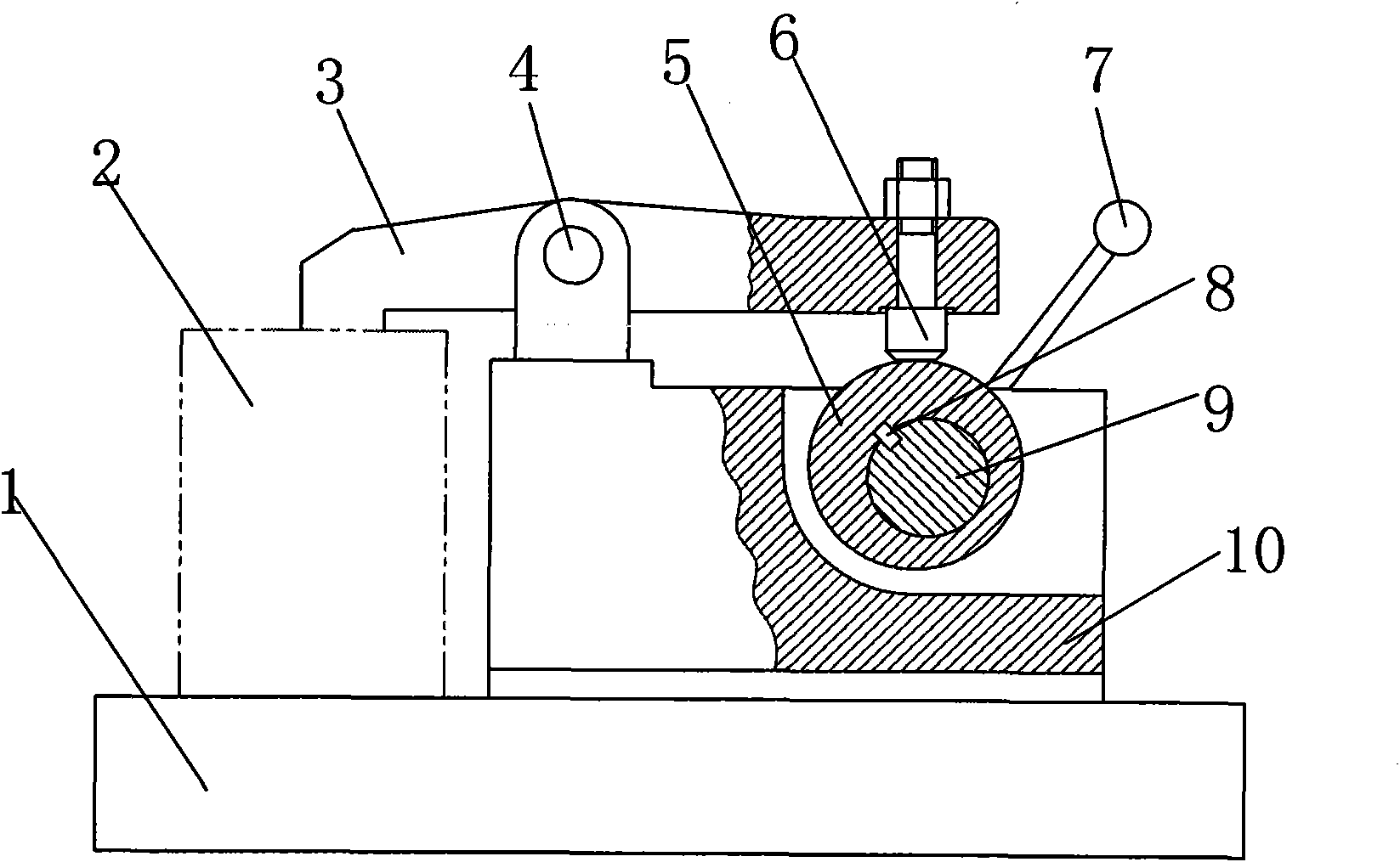
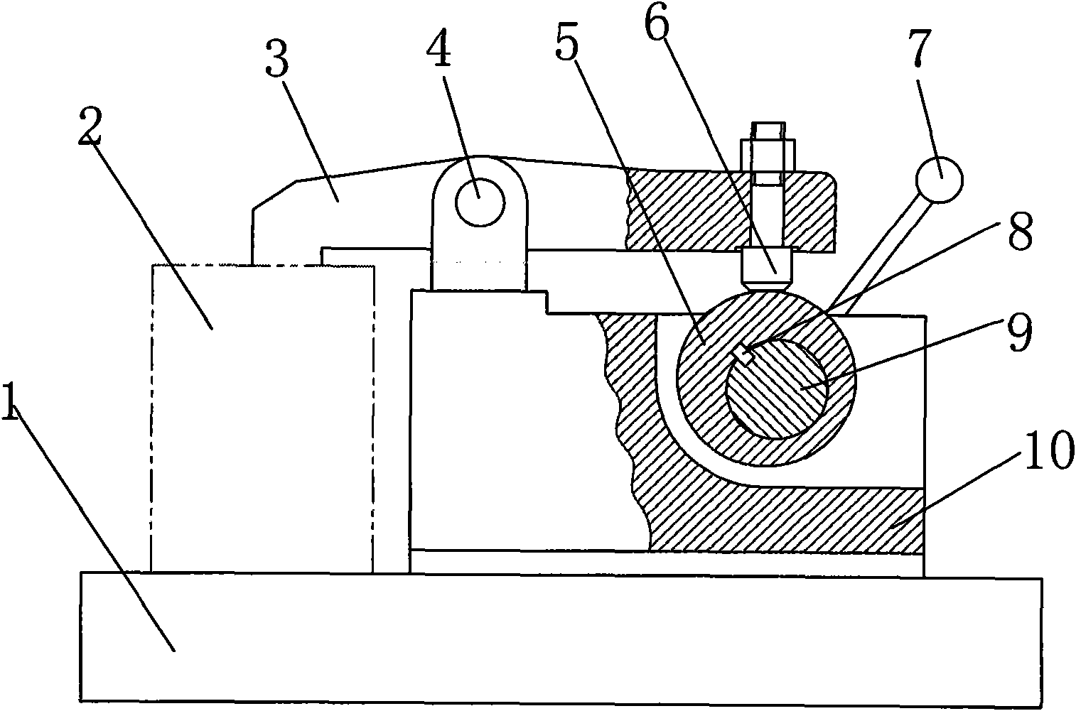
[0010] Cam quick clamping device of the present invention, such as figure 1 As shown, it includes a base 1, a fixed block 10 fixed on the base 1, a pressure rod 3 hinged at one end of the fixed block 10 to form left and right ends, and a cam device connected to the other end of the fixed block 10. The pressing rod 3 is hinged to the fixed block 10 through the pivot pin 4 .

[0011] The cam device includes a final shaft 5, a rotary shaft 9 and a handle 7. The final shaft 5 is provided with an eccentric hole whose diameter matches the diameter of the rotary shaft 9. The rotary shaft 9 is fitted and fixed in the eccentric hole. In this embodiment, the rotary shaft 9 is connected to the final shaft 5 through a key 8. fixed. Both ends of the rotating shaft 9 are movably connected to the fixed block 10, and the handle 7 is fixedly connected to the final shaft 5. A bolt 6 is connected to the right end of the pressing rod 3 and the contact portion of the pressing shaft.


PUM


Abstract

The invention discloses a quick clamping device of a cam, comprising a base [1], a fixed block [10], a pressure lever [3] and a cam device, wherein the fixed block [10] is fixed on the base [1]; the pressure lever [3] is hinged at one end of the fixed block [10] to from a left end and a right end; the cam device is connected with the other end of the fixed block [10] and comprises a pressure shaft [5], a rotating shaft [9] and a handle [7]; the pressure shaft [5] is provided with an eccentric hole the diameter of which is matched with that of the rotating shaft [9]; the rotating shaft [9] is sleeved and fixed in the eccentric hole; two ends of the rotating shaft [9] are movably connected with the fixed block [10]; and the handle [7] is fixedly connected with the pressure shaft [5]. The invention can realize the quick clamping of the workpieces at high clamping efficiency.

Description

technical field [0001] The invention relates to a clamping device, in particular to a device which uses a cam to realize fast clamping. Background technique [0002] In machining, the clamping device is an important processing aid. The workpiece is fixed on the clamping device before it can be turned and milled. Commonly used clamping devices such as the turntable of the lathe and the fixture of the milling machine are all clamped through the connection of nuts and bolts. The disadvantage of the above-mentioned clamping device is that it takes a lot of time to fasten or loosen the nut for clamping and loosening, and the working efficiency is low. Contents of the invention [0003] The purpose of the present invention is to solve the low working efficiency and problems of common clamping devices, and provide a device that utilizes cams to realize fast clamping. [0004] The technical solution adopted by the present invention is: a cam quick clamping device, which is char...

Claims


Application Information

Patent Timeline
Patent Type & Authority Applications(China)
IPC IPC(8): B25B11/00B23Q3/08
Inventor 蒋泽军
Owner 蒋泽军
Why Eureka
Try Eureka