Retarding control system for mining dumper

A mining dump truck and control system technology, which is applied in the direction of control/regulation system, control device, non-electric variable control, etc., can solve the problems of limited vehicle speed, inconvenient operation, high maintenance cost, etc., to improve safety, The effect of simple structure and low cost

Inactive Publication Date: 2013-03-27
SANY HEAVY EQUIP
View PDF3 Cites 0 Cited by
  • Summary
  • Abstract
  • Description
  • Claims
  • Application Information

AI Technical Summary

Problems solved by technology

Before the slow-moving control system is turned on, the rotor of the hydraulic retarder always rotates at the speed output by the turbine. When the operating mechanism turns on the slow-moving control system, the control valve and the valve body assembly are opened, and the hydraulic oil with a certain pressure Entering the retarder shell, the cavity around the hydraulic retarder rotor is filled with hydraulic transmission oil at this time, and the hydraulic oil with a certain viscosity gives a certain resistance to the blades on the hydraulic retarder rotor, limiting Its rotation speed, thus limiting the driving speed of the vehicle
[0004] However, the control system of the existing hydraulic retarder technology is the traditional mechanical handle type operation mode and hydraulic cylinder execution mode. A high degree of attention to observe the driving conditions, as well as precise slow travel travel control, etc., the traditional mechanical handle slow travel operation requires the driver to manually pull or push the control handle, which will inevitably distract the driver's attention, and the operation is inconvenient, slow travel travel The control accuracy is not enough, which causes potential safety hazards; as for the hydraulic cylinder execution method, although it can make up for the shortcomings of the mechanical handle operation method, its structure is complex, and there are many parts in the execution process, which is prone to various failures in actual work. lead to higher maintenance costs

Method used


Image

  • Retarding control system for mining dumper
  • Retarding control system for mining dumper

Examples


Embodiment 1

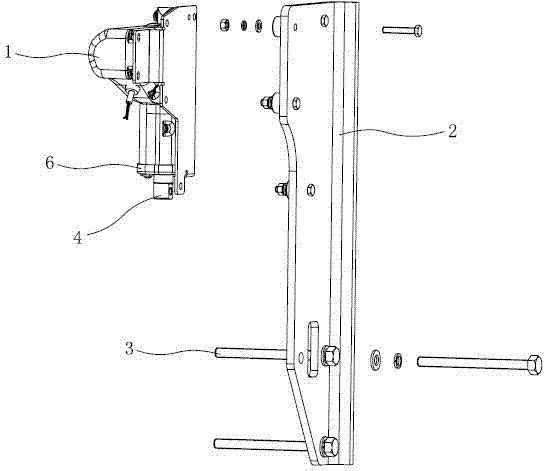
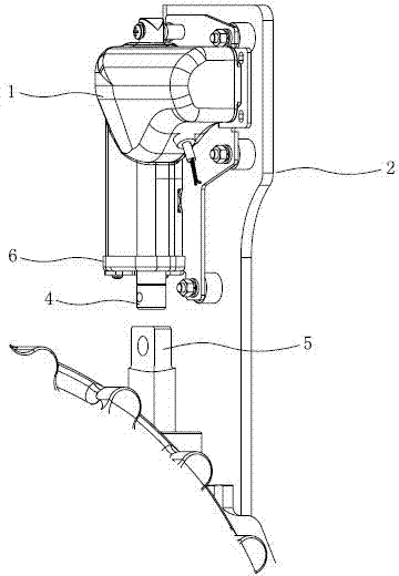
[0020] Embodiment one: see figure 1 , 2 As shown, a slow-moving control system for mining dump trucks includes a slow-moving control assembly arranged on the mining dump truck. The slow-moving control assembly is provided with a slow-moving actuator 1 and a fixed bracket 2. The slow-moving The actuator 1 is connected to the fixed bracket 2, and the fixed bracket 2 is fixedly connected to the mining dump truck through bolts 3. The slow-moving actuator 1 includes a housing in which a motor is arranged, and the output shaft of the motor is decelerated The mechanism is connected with the push rod 4, and the outer end of the push rod 4 is in conflict with the slow-moving valve rod 5 of the gearbox. The clutch and braking mechanism are also equipped with a slow-moving control switch in cooperation with the slow-moving actuator 1. The slow-moving control switch is a seesaw switch, and the slow-moving actuator is provided with a built-in switch at the end of the clutch and the push r...


PUM


Abstract

The invention discloses a retarding control system for a mining dumper, which is characterized by comprising a retarding control assembly arranged on the mining dumper, wherein a retarding executing mechanism and a fixing support are arranged on the retarding control assembly; the retarding executing mechanism is connected with the fixing support; the fixed support is fixedly connected to the mining dumper by bolts; the retarding executing mechanism drives a retarding valve stem of a speed changing box; and a retarding control switch is also matched with the retarding executing mechanism. In the retarding control system, the on-off of the retarding control assembly is controlled by the retarding control switch so as to control the action of the retarding executing mechanism and the action of the retarding valve stem of the speed changing box and implement hydraulic retarding, so the defect of the conventional retarding control is overcome, and the accuracy and safety of the retarding control operation of the mining dumper are improved.

Description

technical field [0001] The invention relates to a control system, in particular to a slow-moving control system of a mining dump truck. Background technique [0002] Mining truck is a mining transport vehicle, which belongs to one of the mining equipment. Due to its large body and high load capacity, mining trucks are mainly used for short-distance transportation of ore and other bulk materials in mines. In mining vehicles, the vehicle transmission slowing device is generally installed, and its main function is to slow down the vehicle when the vehicle is in a curve or downhill. When the car is running on a curve or downhill, it needs to decelerate. Because the total mass of the mining vehicle is relatively large, it needs to overcome a relatively large inertia when decelerating, so that the car will slow down in a short period of time. Under such working conditions, the traditional vehicle control method is for the driver to control the brake system and shift the vehicle t...

Claims


Application Information

Patent Timeline
Patent Type & Authority Patents(China)
IPC IPC(8): B60K31/00B60K23/00
Inventor 闵琪军姚世海陈春根
Owner SANY HEAVY EQUIP
Why Eureka
Try Eureka