Magnetic levitation transferring system

A transmission system, magnetic technology, applied in conveyors, non-mechanical conveyors, transportation and packaging, etc., can solve the problems of damaged components, noise, particles, noise, etc., to achieve the effect of particle generation

Inactive Publication Date: 2011-04-27
SFA ENG CORP
View PDF10 Cites 19 Cited by
  • Summary
  • Abstract
  • Description
  • Claims
  • Application Information

AI Technical Summary

Problems solved by technology

[0018] The object of the present invention is to provide a magnetic levitation transmission system, which uses magnetic levitation technology as one of the non-contact technologies when transporting objects, thereby solving the problem of damage to components due to friction and wear and the problem of causing noise and solving the problem of generating problem of particles, and provide stable and safe power supply while transporting objects at high speed
[0019] Another object of the present invention is to provide a magnetic levitation conveying system, which adopts magnetic levitation technology as one of the non-contact technologies when conveying objects, thereby solving the problem of damage to components due to friction and wear and the problem of causing noise and Solve the problem of particle generation, and especially enable the body transport unit to be transported smoothly in curved sections with relatively very small radii of curvature as well as in straight sections of the track
[0020] Yet another object of the present invention is to provide a magnetic levitation transport system that uses magnetic levitation technology as one of the non-contact technologies when transporting objects, thereby solving the problem of damage to components due to friction and wear and the problem of causing noise and Solve the problem of particle generation and especially prevent vibration or noise generated in the suspension unit or propulsion unit from being transmitted to the loading unit loaded with objects

Method used


Image

  • Magnetic levitation transferring system
  • Magnetic levitation transferring system
  • Magnetic levitation transferring system

Examples


Embodiment Construction

[0043] In order to fully understand the present invention and its advantages, reference will now be made to the accompanying drawings for illustrating embodiments of the invention.

[0044] Hereinafter, the present invention will be described in detail by explaining embodiments of the invention with reference to the accompanying drawings. The same reference numerals in the various drawings represent the same elements.

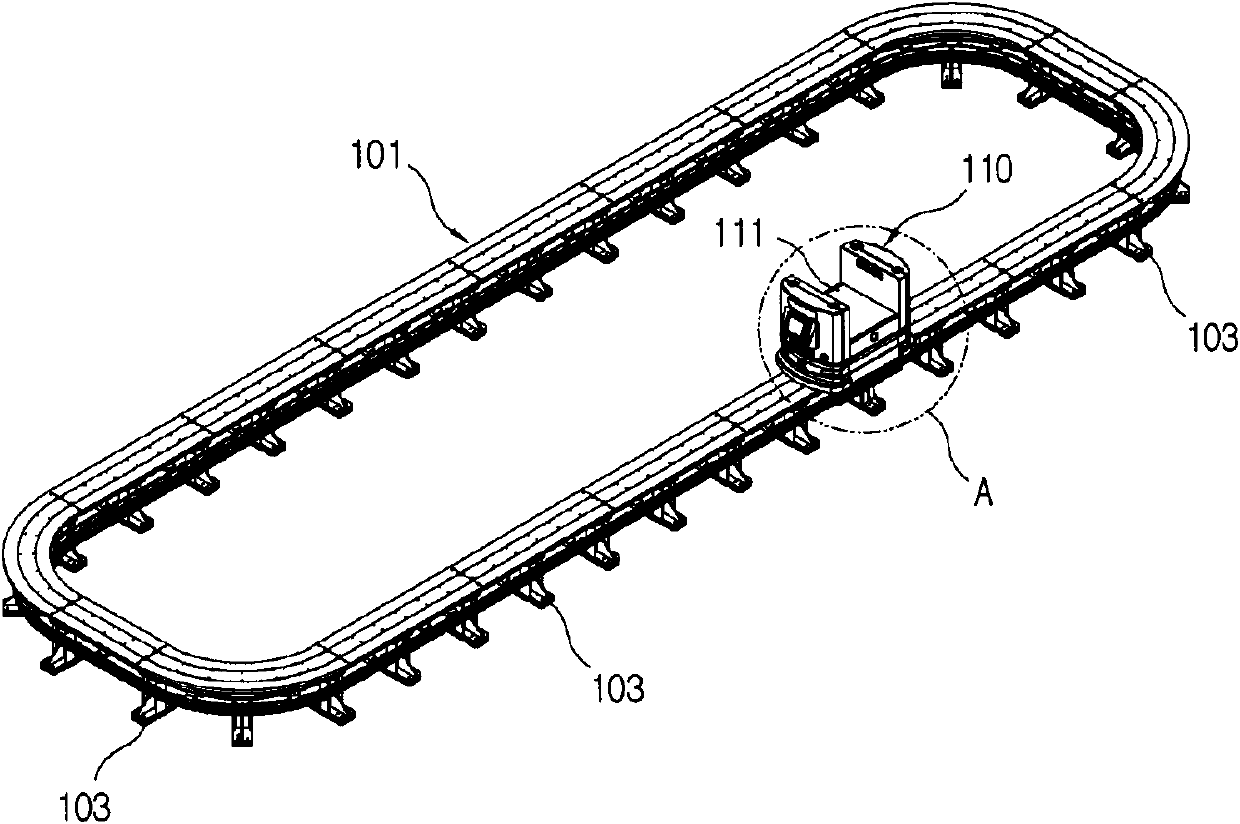
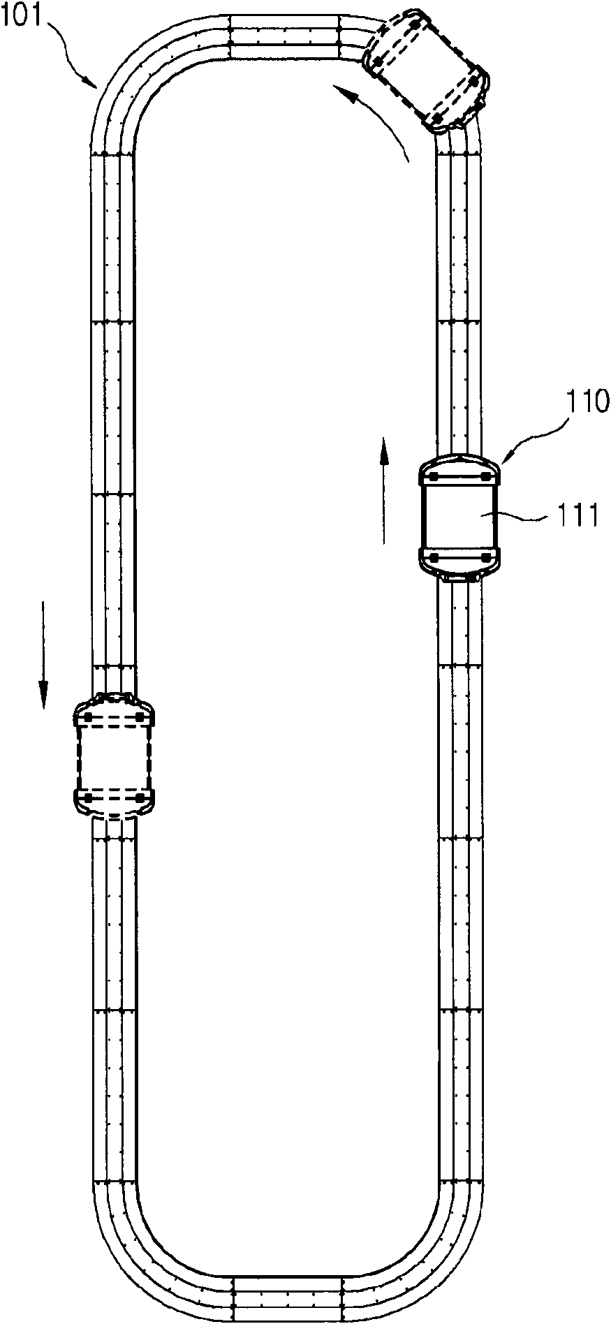
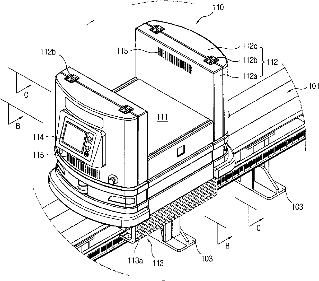
[0045] figure 1 is a perspective view of a magnetic levitation transport system according to an exemplary embodiment of the present invention; figure 2 for figure 1 floor plan; image 3 for figure 1 Enlarged view of area A in ; Figure 4 for image 3 Partially exploded perspective view of excluding orbits; Figure 5 is a partially cut-away perspective view of the main body transmission unit; Figure 6 to Figure 8 is a perspective view of the main transmission unit at different angles; Figure 9 is a partially cut-away perspective view of the main body...


PUM


Abstract

The present invention provides a magnetic levitation transferring system which comprises the following components: a loading unit which is loaded with object; a body transferring unit while the loading unit is coupled to the body transferring unit at one side; a rail which forms a line for transferring the body transferring unit; a levitating unit which is connected with the body transferring unit and causes the body transferring unit to levitate to a preset height relatively to the rail; a pushing unit which is connected with the body transferring unit and provides a pushing force for transferring the body transferring unit levitated by the levitating unit along the line of the rail; and a non-contact power source which receives power through a non-contact mode and supplies power for at least one in the levitating unit and the pushing unit. Through the configuration, a magnetic levitation technique is adopted in transferring object as one of the non-contact techniques thereby settling the problems of assembly damage caused by wearing and abrasion, noise generation and particle generation. Furthermore the power is supplied stably and safely while the object is transferred with a high speed.

Description

[0001] Related Application Cross Reference [0002] This application claims priority to the following Korean patent applications filed at the Korean Intellectual Property Office: No. 10-2009-0090452 filed on September 24, 2009, No. 10-2009-0090453, 10-2009-0090454 filed September 24, 2009, 10-2009-0090455 filed September 24, 2009, and 24 September 2009 No. 10-2009-0090456 filed on January 1, 2009, the disclosures of these Korean patent applications are incorporated herein by reference in their entirety. technical field [0003] The present invention relates to a magnetic levitation transmission system, more specifically, to a magnetic levitation transmission system that adopts magnetic levitation technology as one of the non-contact technologies when transporting objects, thereby solving problems caused by friction and wear. The problem of damaging components and the problem of causing noise and the problem of generating particles are solved, and the power is supplied stably ...

Claims


Application Information

Patent Timeline
Patent Type & Authority Applications(China)
IPC IPC(8): B65G54/02
Inventor 李京南朴浚完宋相旼张宰植
Owner SFA ENG CORP
Why Eureka
Try Eureka