Back cavity-perforated plate-type casing treatment method

A casing processing and perforated plate technology, applied in mechanical equipment, non-variable displacement pumps, machines/engines, etc., can solve the problems of complicated flow in the wall area of ​​the blade tip, blockage of the air flow at the tip, and leakage of the blade tip, and increase the Stable working range, delayed premonitory stall, simple and compact structure

Active Publication Date: 2011-04-27
BEIHANG UNIV
View PDF2 Cites 25 Cited by
  • Summary
  • Abstract
  • Description
  • Claims
  • Application Information

AI Technical Summary

Problems solved by technology

[0005] This is because the traditional casing treatment design is based on the expansion mechanism of the casing treatment to control flow separation. It is believed that the flow at the tip and root of the axial flow compressor is the most complex and harsh, and the stall is usually at the tip or Occurs at the blade root. For a transonic compressor with a high load and high pressure ratio, the flow in the tip wall area is more complicated, the mixing of the tip leakage vortex and the boundary layer of the end wall, the interference of the shock wave and the boundary layer, etc. etc. will cause the flow loss and airflow blockage at the tip. Therefore, if the flow at the tip or the root can be effectively improved, the accumulated boundary layer can be effectively eliminated, the flow loss can be reduced, and the load on the tip can be reduced. Naturally, the stall can be delayed. occur
[0006] The existing casing treatment design based on experience and "trial and error" methods may achieve occasional success by changing the flow field structure in the compressor tip area, but it is difficult to meet the needs of extended stability design. A successful case treatment or patent is used on one type of compressor, while on another compressor either the area of ​​best stabilization effect is off the design point, or it has no effect at all

Method used


Image

  • Back cavity-perforated plate-type casing treatment method
  • Back cavity-perforated plate-type casing treatment method
  • Back cavity-perforated plate-type casing treatment method

Examples


Embodiment Construction

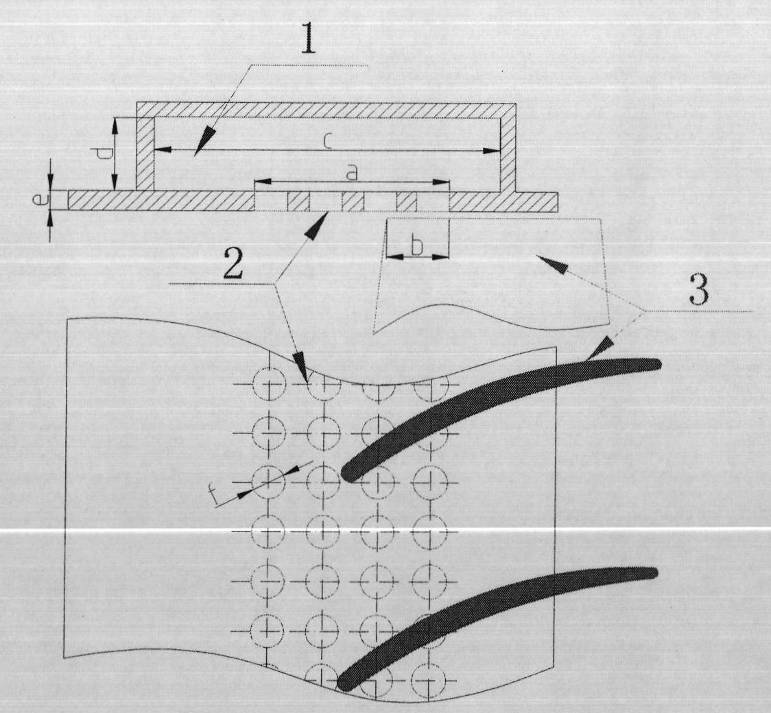
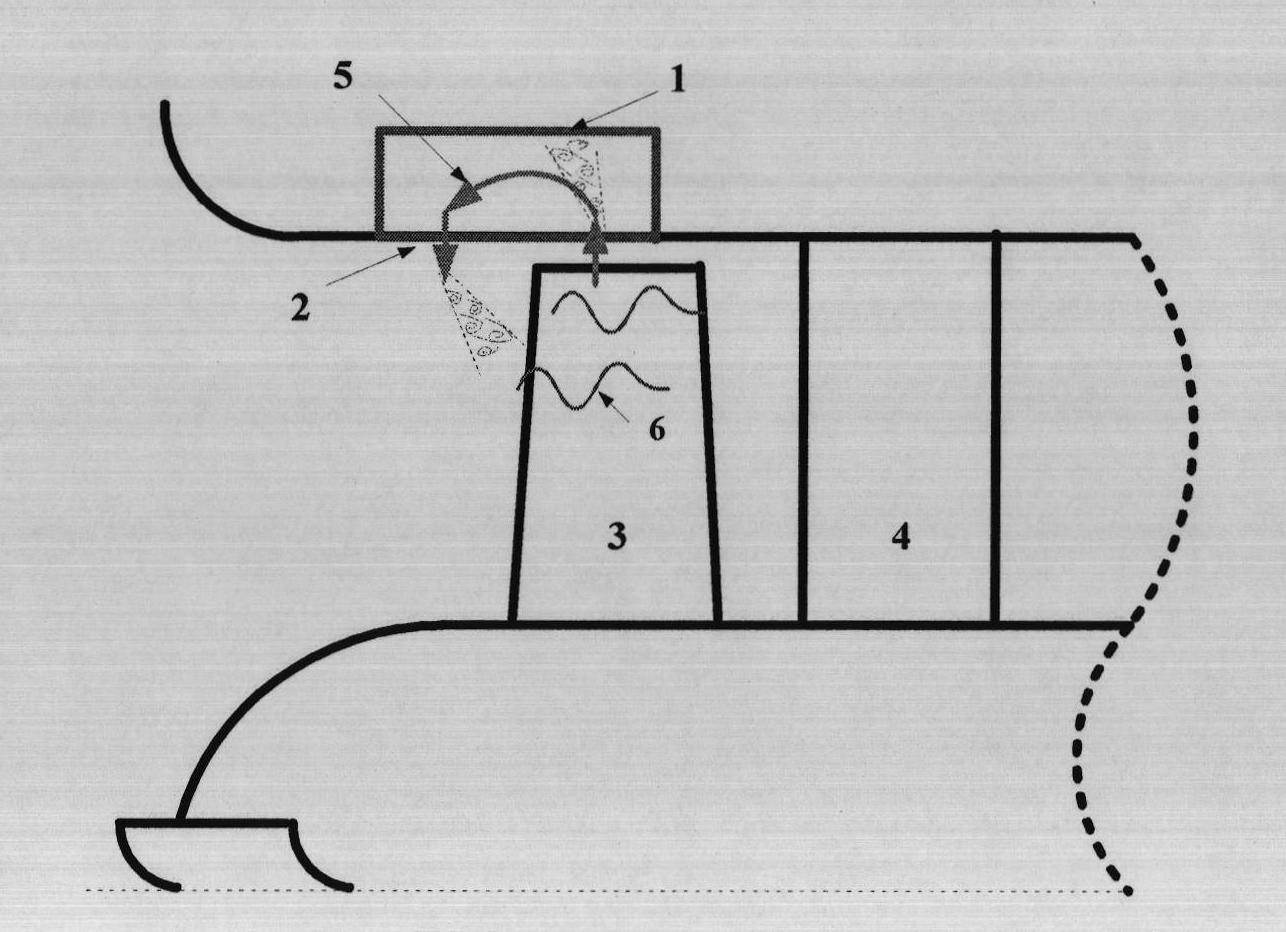
[0020] The cavity-backed perforated plate casing treatment method is to process the cavity-backed perforated plate casing at the leading edge of the compressor rotor to change the boundary conditions of the entire power system to affect its system evolution behavior and achieve the purpose of broadening the stable working range of the compressor. The specific mechanism of action is due to the supercharging effect of the rotor, such as figure 2 As shown, the self-adaptive flow phenomenon 5 that will naturally form in the back cavity 1 is processed in the back cavity perforated plate casing. The inflowing and outflowing airflow will form an unsteady shedding vortex at the edge of the perforated plate 2. When the pressure disturbance wave in the flow field is incident on the unsteady impedance boundary, the wave-vortex interaction mechanism will effectively absorb and dissipate the vortex. Dissipate the energy of the pressure disturbance wave, thereby suppressing the nonlinear a...


PUM


Abstract

The invention discloses a method for treating a back cavity-perforated plate-type casing treatment method. The method comprises the following steps of: designing a casting treater which only comprises an annular back cavity and is provided with a circular hole or an oblique groove perforated hole; and arranging a back cavity-perforated plate-type casing treater at the front end of the rotor inlet of an axial-flow air compressor and covering the back cavity-perforated plate-type casing treater on a position, which corresponds to the front edge part of a rotor blade, of the casing. In the back cavity-perforated plate-type casing treatment method, self-adaptive flow is formed in the back cavity, unsteady shedding vortex is produced on a perforated plate, and the energy of low-frequency disturbance waves in the flow field of the air compressor can be absorbed and dissipated effectively by the interaction of waves and the vortexes and nonlinear amplification of stall inception is suppressed, so that the occurrence of stall inception in the air compressor can be delayed and the stable working range of an air compressor system is expanded; moreover, the mainstream flow field structure of the air compressor is not influenced directly, so that reduction in pressure ratio and efficiency loss of the air compressor system are not caused, a simple and compact structure is achieved and the limiting requirement of engineering on casing size can be met.

Description

technical field [0001] The invention relates to a processing method for a cavity-backed perforated plate type case, which is used for widening the stable operation range of an axial flow compressor, especially for modern high-load transphonic axial flow compressors; the invention belongs to the technical field of turbomachines. Background technique: [0002] As one of the three key components of the air-breathing propulsion system, the axial-flow compressor has been widely used in compression systems of aero-engines, air-breathing cruise missiles, and chemical and energy industries. However, in the design work of modern high-load transonic axial flow compressors, the stability problem represented by rotating stall is particularly prominent, which seriously affects the stable working range of axial flow compressors. As the workload continues to increase, it is more likely to cause insufficient stability of the compressor within the working range. Therefore, the stability desi...

Claims


Application Information

Patent Timeline
Patent Type & Authority Applications(China)
IPC IPC(8): F04D29/54F04D29/38
Inventor 孙晓峰孙大坤景晓东侯睿炜于巍巍王晓宇
Owner BEIHANG UNIV
Why Eureka
Try Eureka