Shell structure for flame tube of aircraft engine
A technology of aero-engines and flame tubes, applied in combustion methods, combustion chambers, combustion equipment, etc., can solve problems such as falling blocks, cracks, and affecting the working life of the whole machine, and achieve the effect of improving uneven temperature distribution
- Summary
- Abstract
- Description
- Claims
- Application Information
AI Technical Summary
Problems solved by technology
Method used
Image
Examples
Embodiment Construction
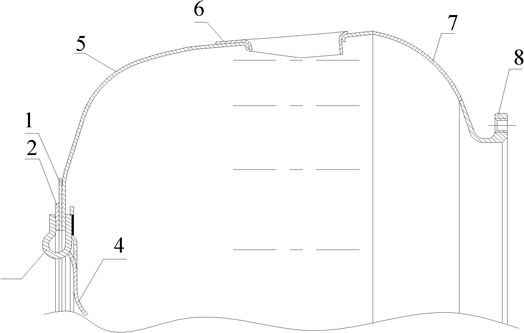
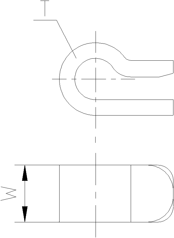
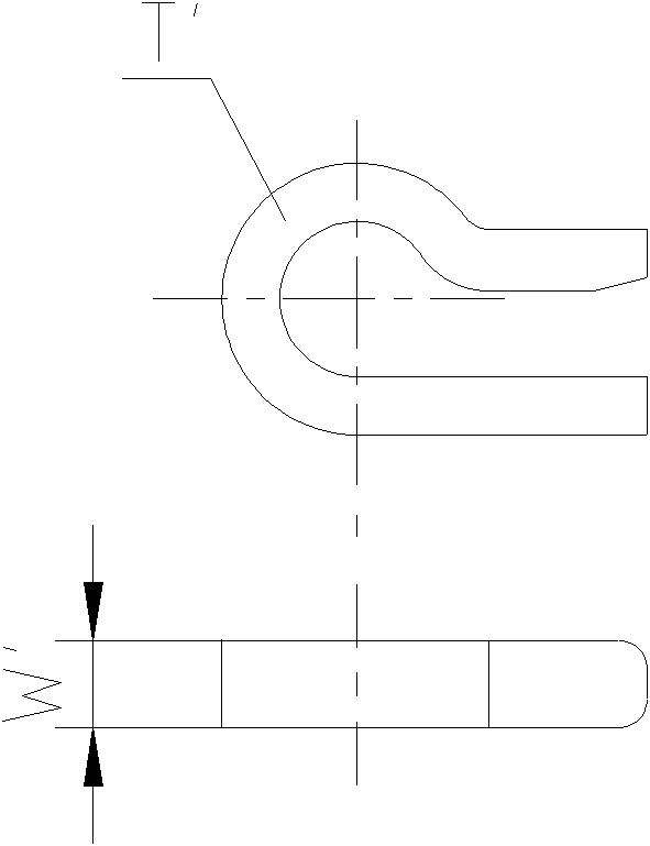
[0024] The improved structure of the flame tube shell of the aero-engine is as follows: figure 1 to Figure 5. The improvement of the fixed hook is that the width W' is changed from the original 11mm to 4.5mm, and the thickness T' of the fixed hook is changed from 1.8mm to 3mm, see Figure 2a , Figure 2b shown. The installation angle of the fixing hook is changed to follow the airflow direction, and the angle θ with the radial axis of the flame tube is 30°, see Figure 3a , Figure 3b shown. By increasing the thickness of the fixing hook, the gap S between the front air intake cone and the flame tube shell is increased from the original 1.8mm to the current 2.4mm, such as Figure 4 shown. The narrow fixing hook placed along the airflow direction effectively eliminates the airflow separation area behind the original fixing hook, so that the cooling air film can flow more evenly and continuously along the wall surface, thereby reducing the temperature of the front wall sur...
PUM
 Abstract
Description
Claims
Application Information
 - R&D
- Intellectual Property
- Life Sciences
- Materials
- Tech Scout
- Unparalleled Data Quality
- Higher Quality Content
- 60% Fewer Hallucinations
Browse by: Latest US Patents, China's latest patents, Technical Efficacy Thesaurus, Application Domain, Technology Topic, Popular Technical Reports.
© 2025 PatSnap. All rights reserved.Legal|Privacy policy|Modern Slavery Act Transparency Statement|Sitemap|About US| Contact US: help@patsnap.com


