Direct current micro voltage/micro current detection device and detection method thereof

A detection device and micro-current technology, applied in the direction of indicating the existence of current/voltage, using digital measurement technology for measurement, etc., can solve the discomfort of measuring microampere-level current or microvolt-level voltage, prone to deviation, and inability to do so To the microampere, microvolt level and other problems, to achieve the effect of effective detection device and detection method

Inactive Publication Date: 2012-10-31
漳州国绿太阳能科技有限公司
View PDF0 Cites 0 Cited by
  • Summary
  • Abstract
  • Description
  • Claims
  • Application Information

AI Technical Summary

Problems solved by technology

However, when using a comparator, it is necessary to use a known voltage or current as a reference, which is prone to deviations, thereby affecting the accuracy. In particular, the current general-purpose comparator has only an accuracy of 0.01 volts, and there is also the problem of limited accuracy, so Comparators are also not suitable for measuring microampere-level currents or microvolt-level voltages
In addition, Hall devices can also be used to measure unknown voltages or currents, but since Hall devices can only measure milliamps and millivolts, they cannot measure microamps and microvolts, so they cannot be used to measure microvoltages or currents. microcurrent
Obviously, the detection technology for DC micro-voltage and micro-current is basically blank at present.

Method used


Image

  • Direct current micro voltage/micro current detection device and detection method thereof
  • Direct current micro voltage/micro current detection device and detection method thereof

Examples


Embodiment Construction

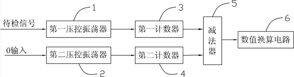
[0019] Examples, see figure 1 As shown, a kind of DC microvoltage / microcurrent detecting device of the present invention comprises an oscillating circuit, a digital signal amplifying circuit, a subtractor 5 and a value conversion circuit 6; the oscillating circuit comprises two completely identical parameters A voltage-controlled oscillator 1 and a second voltage-controlled oscillator 2; the digital signal amplifying circuit includes two first counters 3 and second counters 4 with identical parameters; the input of the first voltage-controlled oscillator 1 is output by the detection signal Terminal, the input of the second voltage-controlled oscillator 2 is grounded, that is, connected to the 0 input terminal; the outputs of the first voltage-controlled oscillator 1 and the second voltage-controlled oscillator 2 correspond to the first counter 3 and the second counter 4 respectively. The input is connected; the outputs of the first counter 3 and the second counter 4 are respec...


PUM


Abstract

The invention discloses a direct current micro voltage / micro current detection device and a detection method thereof. The detection device comprises an oscillation circuit, a digital signal amplifying circuit, a subtractor and a numerical value scaling unit, wherein the oscillation circuit comprises a first voltage-controlled oscillator and a second voltage-controlled oscillator, the parameters of the first voltage-controlled oscillator and the second voltage-controlled oscillator are the same, the input of the first voltage-controlled oscillator is connected with the output end of a signal to be detected or is grounded, the input of the second voltage-controlled oscillator is grounded or is connected with the output end of the signal to be detected, the output of the first voltage-controlled oscillator and the output of the second voltage-controlled oscillator are respectively connected with the input of the digital signal amplifying circuit; the output of the digital signal amplifying circuit is connected with the input of the subtractor, and the output of the subtractor is connected with the input of the numerical value scaling unit. The method comprises the following steps: the detection device respectively converts an input signal into oscillation frequencies by the first voltage-controlled oscillator and the second voltage-controlled oscillator, and amplifying, subtracting and conversion are carried out, so as to judge whether a direct current micro voltage or direct current micro current is input or not.

Description

technical field [0001] The invention relates to a DC voltage / current detection device, in particular to a detection device capable of detecting microvolt-level DC voltage or microampere-level DC current and a detection method thereof. Background technique [0002] At present, if you want to measure an unknown voltage or current, a digital multimeter is undoubtedly a better choice. The digital multimeter can not only achieve fast measurement, but also intuitively see the measurement results. However, since the digital multimeter can only display 0.01 amps at 20 amps, its accuracy is limited, and it is only suitable for measuring larger currents or voltages, but it is helpless for microampere-level currents or microvolt-level voltages. . In addition to digital multimeters, comparators are also a good choice. However, when using a comparator, it is necessary to use a known voltage or current as a reference, which is prone to deviations, thereby affecting the accuracy. In part...

Claims


Application Information

Patent Timeline
Patent Type & Authority Patents(China)
IPC IPC(8): G01R19/25G01R19/145
Inventor 曾少南
Owner 漳州国绿太阳能科技有限公司
Why Eureka
Try Eureka