
System for testing dynamic parameter of high-speed electromagnetic valve for knitting machine

A high-speed solenoid valve and dynamic parameter technology, applied in circuit breaker testing and other directions, can solve problems such as lack of detection, lagging detection methods, and inability to detect product dynamic response performance, and achieve the effect of convenient use and reliable operation.

Inactive Publication Date: 2011-04-27
CHANGSHU INSTITUTE OF TECHNOLOGY
View PDF5 Cites 23 Cited by
  • Summary
  • Abstract
  • Description
  • Claims
  • Application Information

AI Technical Summary

Problems solved by technology

[0004] At present, enterprises that produce high-speed solenoid valves for knitting machinery have relatively lagging detection methods, and most of them can only complete the detection of part of the electromagnetic parameters of the solenoid valve. At present, it is impossible to detect the dynamic response performance of the product.
At the same time, the existing solenoid valve dynamic parameter detection equipment at home and abroad is mainly aimed at solenoid valves for automobiles, solenoid valves for hydraulic control systems, etc. Currently, there is no special equipment for dynamic parameters of high-speed solenoid valves for knitting machinery on the market
[0005] The domestic existing solenoid valve parameter detection equipment for knitting machinery mainly detects the electromagnetic parameters of the solenoid valve, such as the cold state DC resistance of the solenoid valve coil, the cold state insulation resistance between the coil and the iron core, and the DC resistance of the solenoid valve. Excitation voltage, DC excitation current, magnetic induction intensity at a fixed distance, etc., cannot accurately measure the time parameters of the dynamic process of solenoid valve pull-in and release, and real-time mapping of current and voltage parameters

Method used

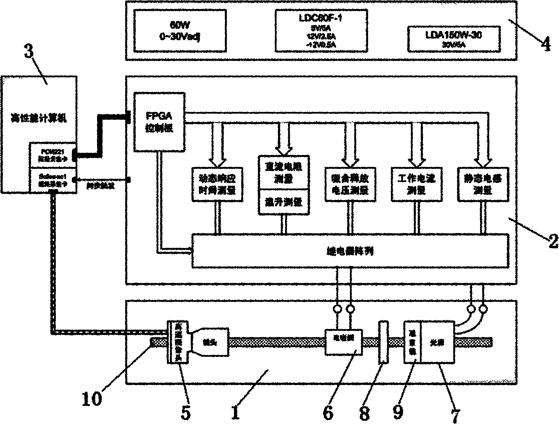
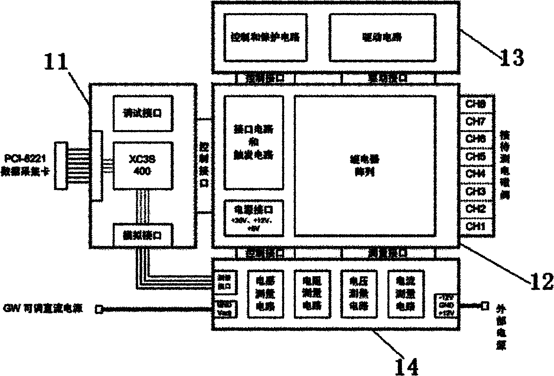

Image

  • System for testing dynamic parameter of high-speed electromagnetic valve for knitting machine
  • System for testing dynamic parameter of high-speed electromagnetic valve for knitting machine
  • System for testing dynamic parameter of high-speed electromagnetic valve for knitting machine

Examples


Embodiment Construction

[0036] Such as figure 1 , 2 As shown, the test system of the present invention is composed of four parts: a test bench 1 , a measurement and control circuit board 2 , a host computer 3 and an external power supply module 4 .

[0037] The main body of the test bench 1 is an optical bench, which is equipped with a movable clamping mechanism for fixing the high-speed line array camera 5, the electromagnetic valve to be tested 6, the light source 7 and other related equipment. The high-speed line array camera 5 is coaxial with the spool of the solenoid valve 6 to be tested and the light source 7, and the camera 5 captures the action images of the spool of the solenoid valve 6 to be tested for analysis by the host computer. The test bench 1 provides measurement terminals for connecting the solenoid valve 6 to be tested and the measurement and control circuit board 2 .

[0038] The measurement and control circuit board 2 takes FPGA as the control core, and includes the interface c...


PUM


Abstract

The invention discloses a system for testing the dynamic parameter of a high-speed electromagnetic valve for a knitting machine. The system comprises a testing table (1), a measurement and control circuit board (2), an upper computer (3) and an external power supply module (4), wherein the upper computer (3) comprises a data acquisition card and an image acquisition card; the data acquisition card is used for communicating with the measurement and control circuit board (2) and measuring a voltage signal to be tested, which is output by the measurement and control circuit board (2); and the image acquisition card is used for synchronously acquiring and storing output data of a high-speed line scanning camera (5) and has the function of synchronously triggering a measurement interface circuit board (12). In the system, by adopting a machine vision-based non-contact measurement method and a design method of a virtual instrument, using a general computer and the data acquisition card and combining a self-developed hardware testing platform, the dynamic response time of the electromagnetic valve is accurately measured, and necessary testing data is provided for the design and inspection of electromagnetic valve products.

Description

technical field [0001] The invention relates to a dynamic parameter test system of a solenoid valve, in particular to a dynamic parameter test system of a high-speed solenoid valve for knitting machinery. Background technique [0002] Knitting machinery is the necessary production equipment for the production of knitted fabrics and knitted garments such as woolen sweaters. In recent years, with the increasing demand for knitted fabrics and clothing in the international and domestic markets, domestic knitting machinery manufacturing Machine production has developed rapidly, but currently high-performance knitting machines still mainly rely on imports. At the same time, there is still a lack of comprehensive and systematic research and development on the key components of knitting machinery in China, which also restricts the improvement of the performance of the knitting machinery to a certain extent. [0003] Solenoid valves are widely used in knitting machinery, with many t...

Claims


Application Information

Patent Timeline
IPC IPC(8): G01R31/327
Inventor 华强霍铖宇卢达范龙保徐刚李新
Owner CHANGSHU INSTITUTE OF TECHNOLOGY
Learn More