Optical unit and backlight unit using the same

A technology of optical unit and backlight unit, which is applied in the direction of optical components, optics, nonlinear optics, etc., and can solve the problems of general products without structure and inconvenience

A technology of optical unit and backlight unit, which is applied in the direction of optical components, optics, nonlinear optics, etc., and can solve the problems of general products without structure and inconvenience

CN102033253AActive Publication Date: 2011-04-27KEIWA INCORPORATED

Image

  • Optical unit and backlight unit using the same
  • Optical unit and backlight unit using the same
  • Optical unit and backlight unit using the same

Examples


Embodiment

[0118] Hereinafter, although this invention is demonstrated in full detail based on an Example, this invention is not limitedly interpreted based on description of this Example.

[0119]

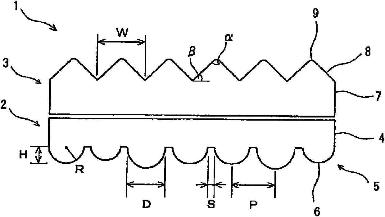
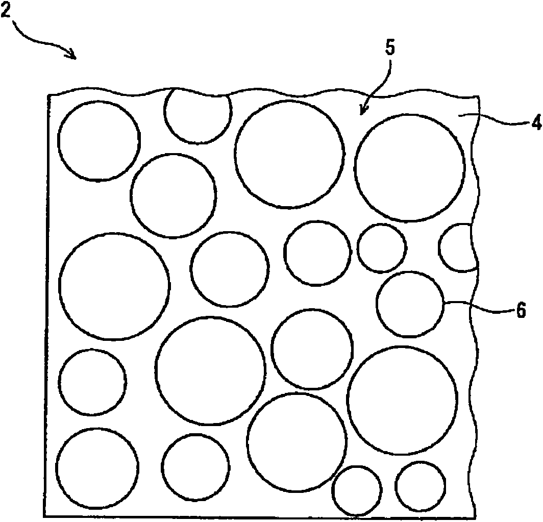
[0120] A microlens sheet is formed by laminating molten polycarbonate resin on a reverse-shaped sheet mold having a microlens array, and peeling off the sheet mold. The formed microlens sheet had an average thickness of 100 μm, an average microlens diameter of 60 μm, and a microlens diameter variation coefficient of 50%.

[0121]

[0122] A prism sheet is formed by laminating molten polycarbonate resin on a sheet mold having a reverse shape of the prism sheet and peeling off the sheet mold. The formed prism sheet was formed with an average thickness of 100 μm and a width of the bottom surface of the rib prism portion of 100 μm.

[0123] [Example]

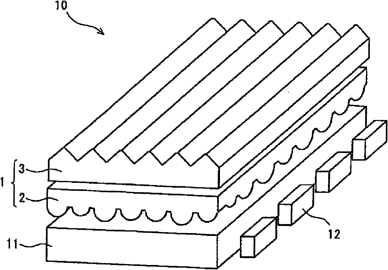
[0124] Light emitting diodes were arranged as light sources on the side end surfaces of the light guide plate with a thickness of 3 mm. On...


PUM

PropertyMeasurementUnit
The average diameteraaaaaaaaaa
The average thicknessaaaaaaaaaa

Abstract

The invention relates to an optical unit and a backlight unit using the same. The optical unit has relative high optical function such as refraction towards the normal direction side and wide-angle light diffusion and easily and accurately controls the optical function. The backlight unit using the optical unit promotes the improvement of the quality such as high luminance towards the front direction, wide visual angle and lightness uniformization. The optical unit comprises a micro-lens sheet material and a prismatic lens sheet material arranged on the surface side of the micro-lens sheet material and the micro-lens sheet material comprises a micro-lens array comprising a plurality of micro-lens on the back and the prismatic lens sheet material comprises a protuberance array comprising aplurality of protuberance prismatic parts on the surface. The variation coefficient of the diameter of the micro-lens in the micro-lens sheet material is preferably more than 30%, below 100%.

Description

technical field [0001] The present invention relates to an optical unit suitable for a backlight unit of a liquid crystal display device having excellent surface uniformity and a wide viewing angle, especially a liquid crystal display device for a car navigation system, and a backlight unit using the optical unit. Background technique [0002] Liquid crystal display devices are widely used as display devices for screens of televisions and personal computers, and are broadly classified into direct-view type for directly viewing a display screen and projection type for viewing images projected on a screen. Among the direct-view liquid crystal display devices, there are transmissive ones that transmit light from the backlight, reflective ones that use natural light or reflected light from indoor lights without a backlight, and semi-reflective ones that are reflective in bright places and transmissive in dark places. Transmissive. On the other hand, projection type liquid cryst...

Claims


Application Information

Patent Timeline
27 Apr 2011
Publication
CN102033253A
IPC
G02B5/02; G02F1/13357; F21V5/02
CPC
G02B5/0231; G02B5/0242; G02B5/045; G02B6/0038; G02B6/0053; G02F1/133607
Inventors
冈部元彦; 峯尾裕