Cable reel

A wire reel and cable technology, which is applied in the direction of bendable lead devices, current collectors, electrical components, etc. The effect of uniformity, improved withstand voltage, and improved reliability

Inactive Publication Date: 2011-04-27
NINGBO LANBAO ELECTRIC APPLIANCE
View PDF0 Cites 0 Cited by
  • Summary
  • Abstract
  • Description
  • Claims
  • Application Information

AI Technical Summary

Problems solved by technology

The existing reels basically include cables, take-up reels, conductive terminals, etc., which are used to lead the remote power supply to the power consumption place. The arrangement of the conductive terminals of the existing reels is basically arranged on the same straight line, but this This design has the following defects: when the diameter of the wire reel is determined, the distance between two adjacent terminals is relatively close, which will lead to a decrease in the withstand voltage value; and if the distance between two adjacent terminals is adjusted to increase the withstand voltage value, it will be in On the whole, the diameter of the entire wire reel is increased, resulting in an increase in the volume of the entire wire reel, which is inconvenient to use; in addition, the existing linear arrangement method will also appear uneven force during use, and the wire reel is in the process of taking up or paying off the wire. Sometimes there will be problems such as wire reel swing, resulting in unreliable use

Method used


Image

  • Cable reel
  • Cable reel
  • Cable reel

Examples


Embodiment Construction

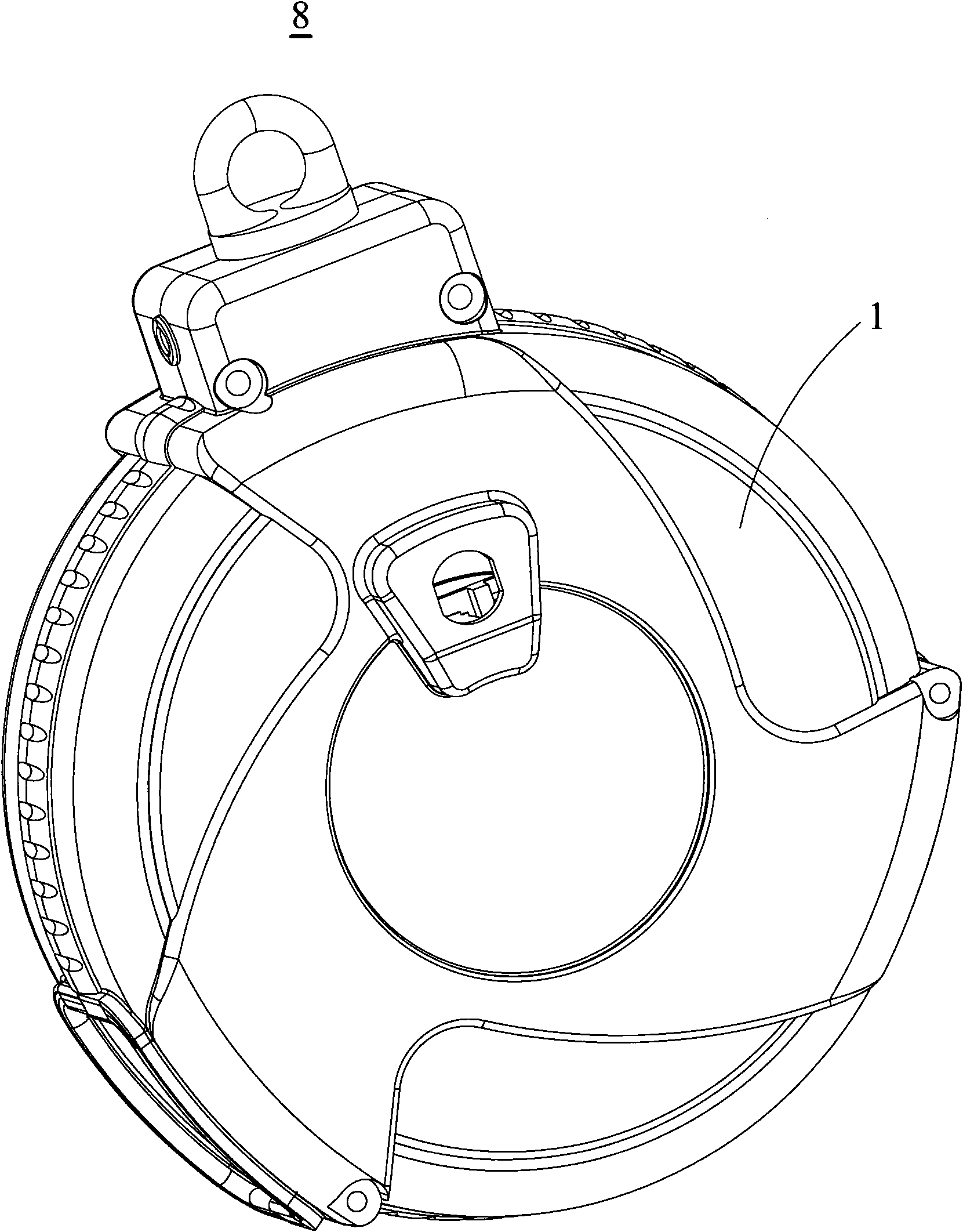
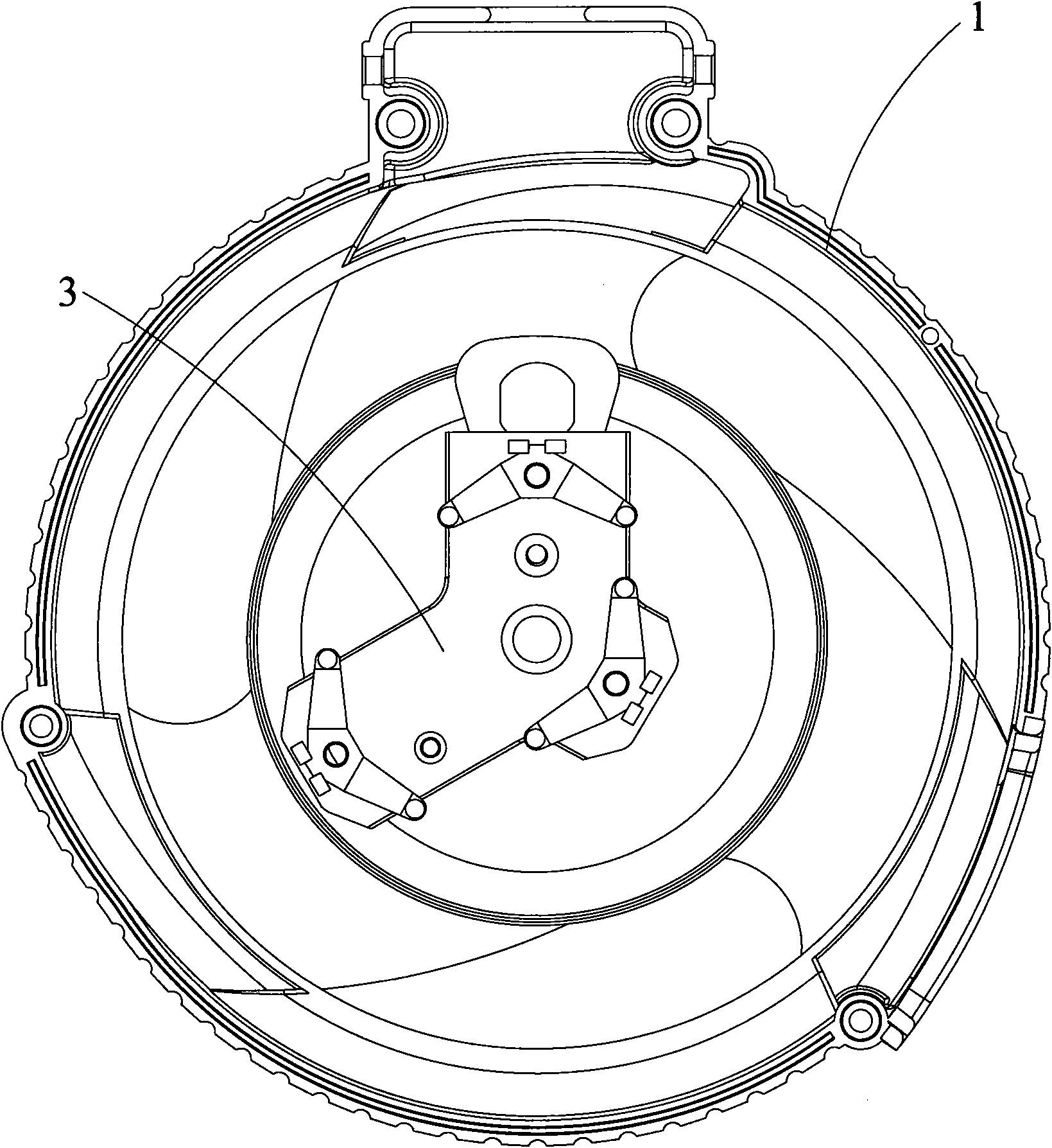
[0014] see Figure 1-Figure 5 As shown, the wire reel 8 of the present invention includes a housing 1 , a runner (not shown), cables (not shown), a track module 2 and a terminal module 3 accommodated in the housing 1 . The cable is wound on the wheel, and one end is electrically connected to the track module 2 or the terminal module 3 .

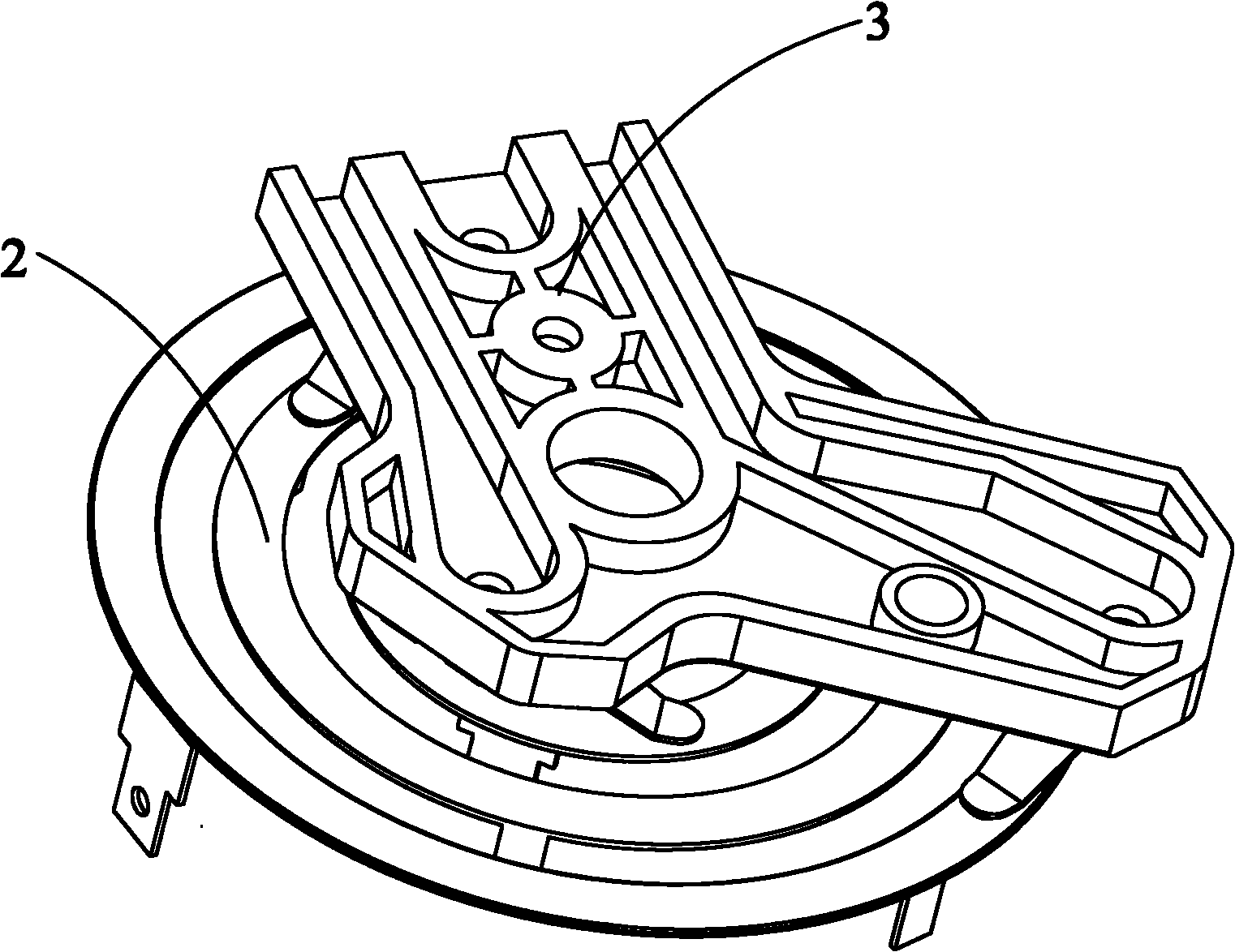
[0015] Please also refer to Figure 5 As shown, the track module 2 includes first, second, and third conductive tracks 21, 22, and 23 formed in a circle by a plurality of concentric rings, and a track module fixing part 24. The track module 2 It is fixed on the runner by the fixing part 24 .

[0016] Please also refer to Figure 4 As shown, the terminal module 3 includes first, second, third conductive terminals 31, 32, 33 and a terminal fixing base 34. The terminal base 34 is roughly flat and includes first, second, third Terminal fixing parts 341, 342, 343, the first, second, third conductive terminals 31, 32, 33 are respectively fixed ...


PUM


Abstract

The invention relates to a cable reel comprising a cable, a rotating wheel, a track module and a terminal module. The cable is wound on the rotating wheel, and one end of the cable is electrically connected with the terminal module or the track module. The track module comprises a first conductive track, a second conductive track and a third conductive track. The terminal module comprises a first conductive terminal, a second conductive terminal and a third conductive terminal, the first, the second and the third conductive terminals respectively come into independent electric contact with the first, the second and the third conductive tracks, and the first, the second and the third conductive terminals are mutually arranged on the same plane at an angle of 120 DEG.

Description

【Technical field】 [0001] The present invention relates to wire take-up technology, more precisely, relates to a wire winding reel, which belongs to the technical field of wire reel structure. 【Background technique】 [0002] In daily life and work, it is often encountered that the power supply port is far away from the power consumption place, such as holding outdoor activities or field operations, etc. In these cases, the use of the wire reel is frequent. The existing reels basically include cables, take-up reels, conductive terminals, etc., which are used to lead the remote power supply to the power consumption place. The arrangement of the conductive terminals of the existing reels is basically arranged on the same straight line, but this This design has the following defects: when the diameter of the wire reel is determined, the distance between two adjacent terminals is relatively close, which will lead to a decrease in the withstand voltage value; and if the distance be...

Claims


Application Information

Patent Timeline
IPC IPC(8): H01R39/64H01R13/72
Inventor 王爱庆
Owner NINGBO LANBAO ELECTRIC APPLIANCE
Why Eureka
Try Eureka