Thermal flow sensor for vehicles

Inactive Publication Date: 2013-03-21
MITSUBISHI ELECTRIC CORP
View PDF6 Cites 0 Cited by
  • Summary
  • Abstract
  • Description
  • Claims
  • Application Information

AI Technical Summary

Benefits of technology

The thermal flow sensor for vehicles described in this patent is designed to easily ensure the necessary power for heating the resistor in the bridge circuit unit, while also protecting the integrated circuit unit from battery line overvoltage and surge without the need for additional components. This results in a more efficient and effective thermal flow sensor design for vehicles.

Problems solved by technology

This imposes the constraint that the material for the heating resistor is limited.

Method used


Image

  • Thermal flow sensor for vehicles
  • Thermal flow sensor for vehicles
  • Thermal flow sensor for vehicles

Examples


first embodiment

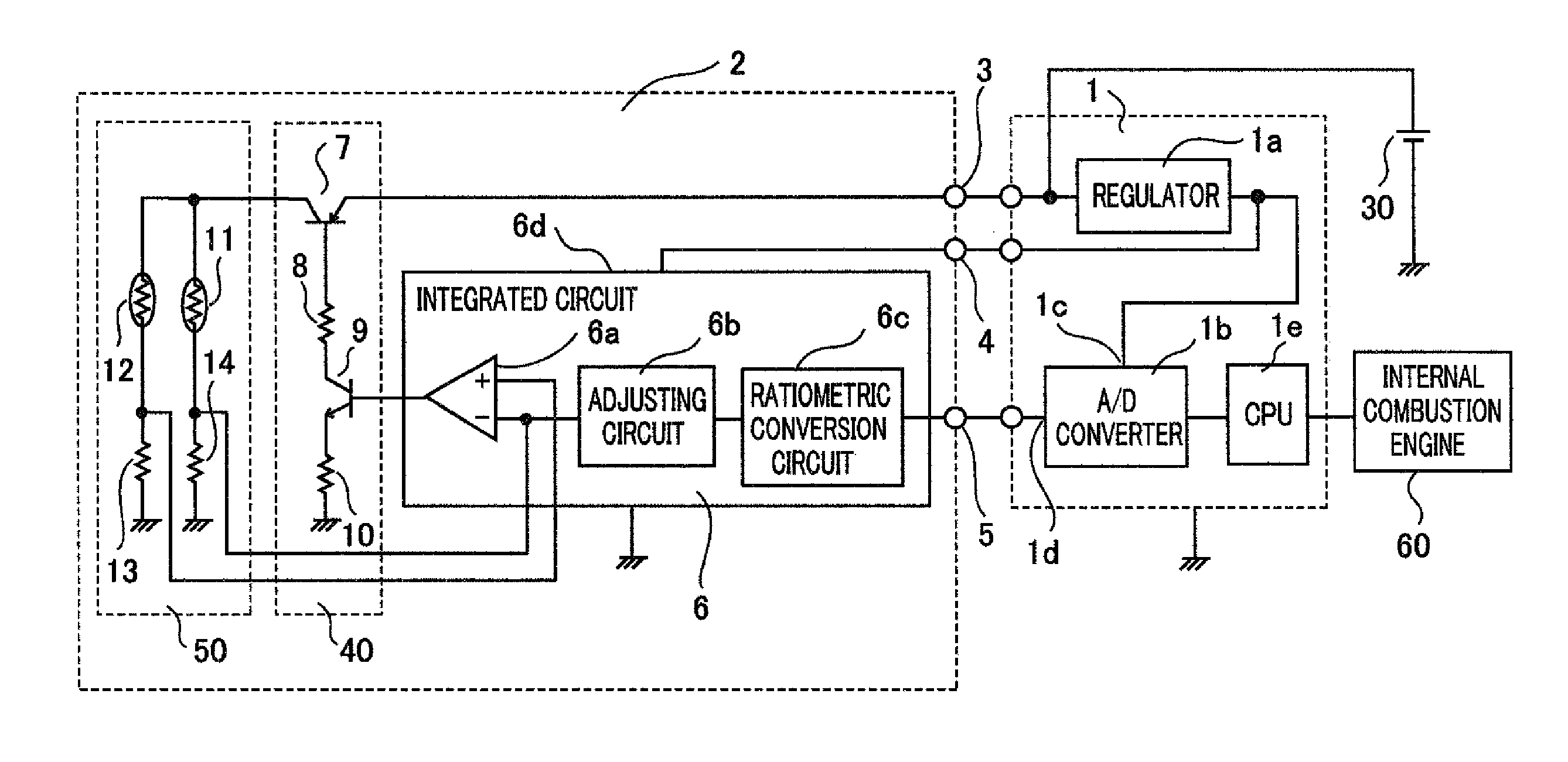
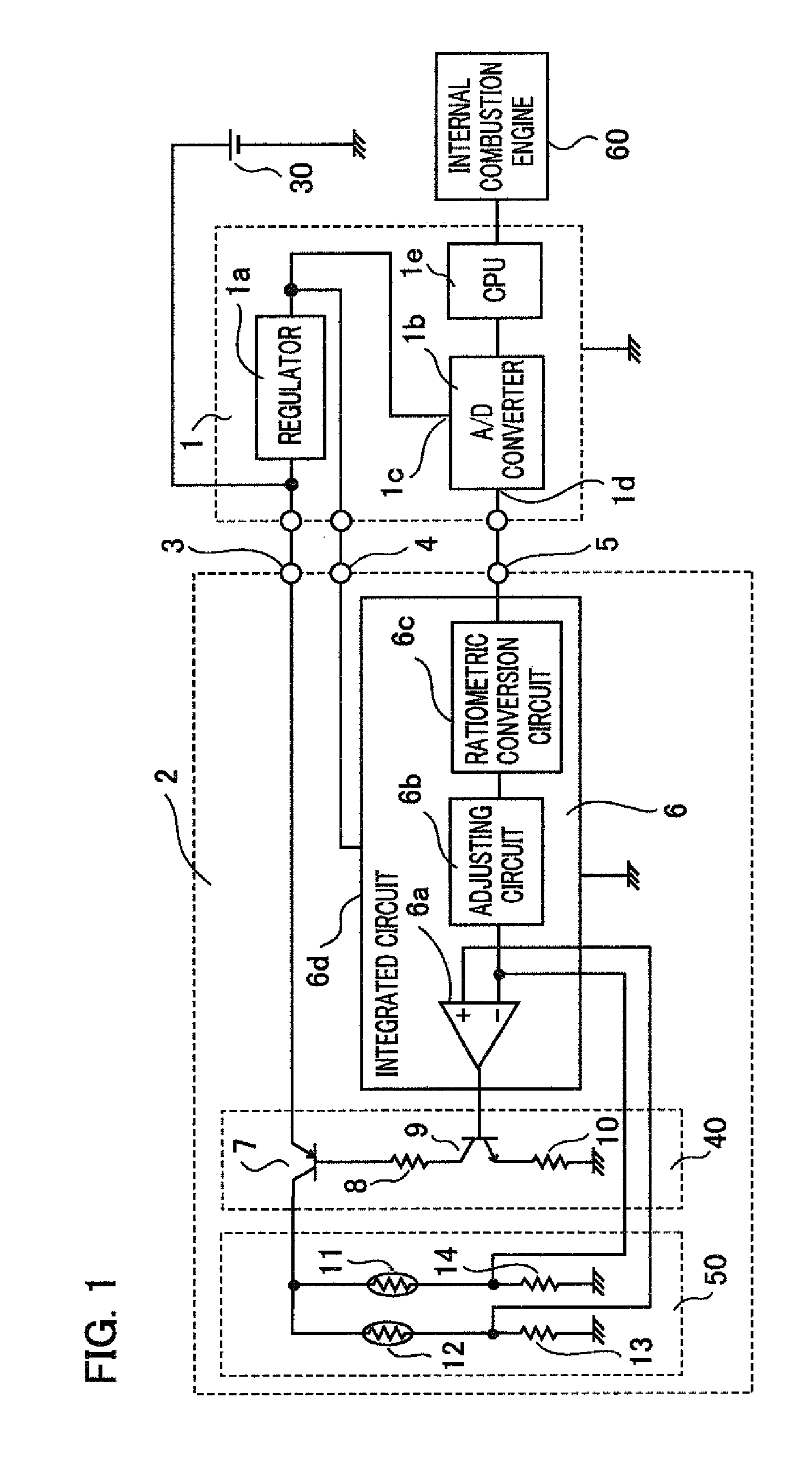
[0017]FIG. 1 is a circuit diagram showing a thermal flow sensor for vehicles according to a first embodiment of this invention. The first embodiment pertains to a thermal flow sensor for vehicles used for, for example, an automobile that has a battery and an internal combustion engine controlled by a fuel injection control device. The thermal flow sensor for vehicles is disposed at a combustion air inlet pipe of an engine to measure the flow rate of the inlet air. A fuel injection control device 1 has a regulator 1a. The regulator 1a controls the voltage supplied from a battery 30 so as to be a predetermined voltage at all times, and outputs a constant voltage. A constant voltage source that outputs a predetermined voltage is obtained by the battery 30 and the regulator 1a. The voltage that is output from the regulator 1a (i.e., the voltage of the constant voltage source) is applied to a reference voltage terminal 1c of an A / D converter 1b disposed in the fuel injection control devi...

second embodiment

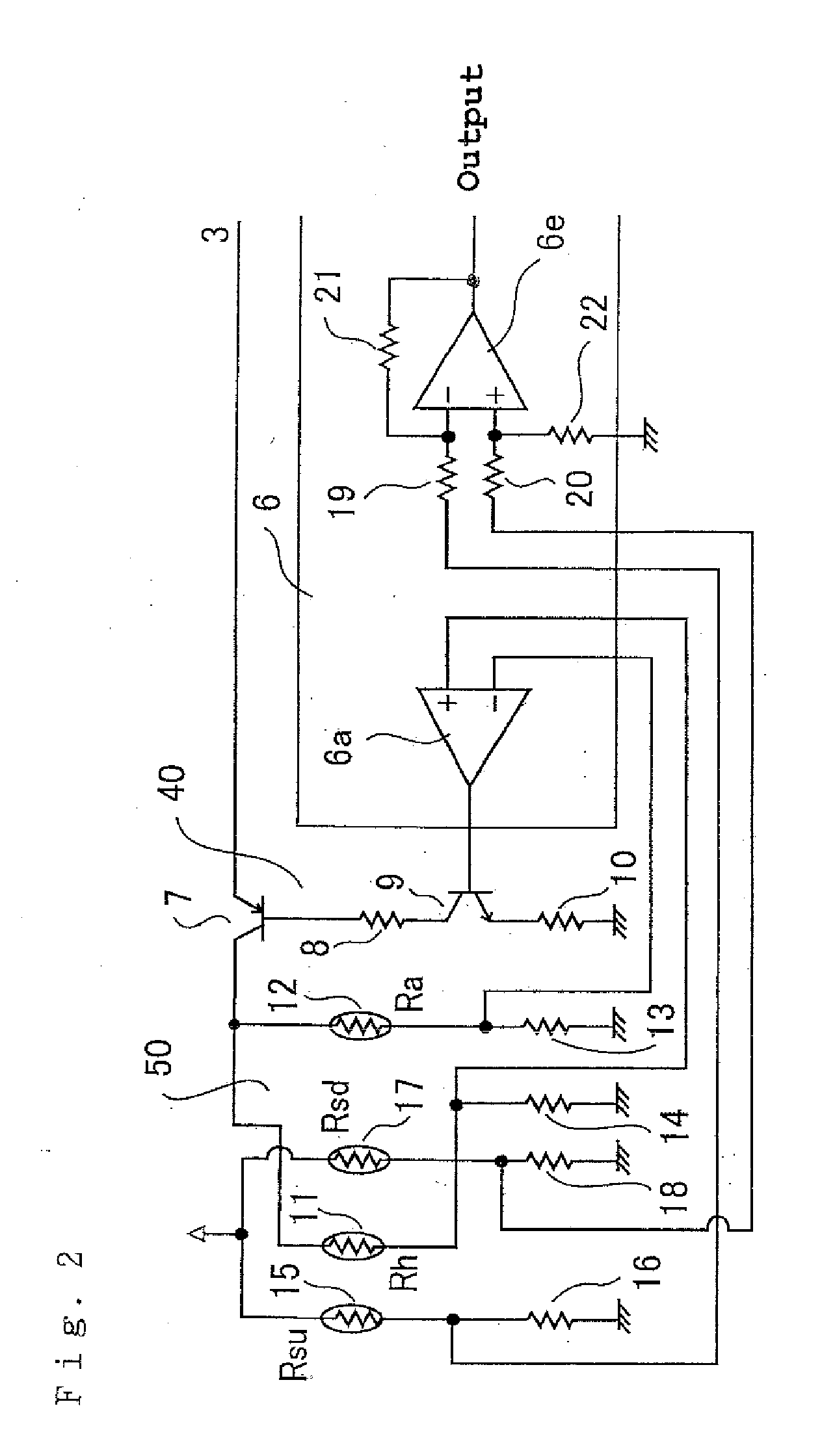
[0026]The thermal flow sensor for vehicles causes a resistor whose resistance value changes according to temperature to produce heat, and there are plural types of thermal flow sensors for vehicles that use a bridge circuit unit having a heating resistor and an integrated circuit unit. This invention is applicable to any of the types. FIG. 2 is a circuit diagram showing a primary portion of a thermal flow sensor for vehicles according to a second embodiment. In the drawings, the same reference symbols refer to the same or corresponding parts, and the description thereof is partially omitted. Reference numeral 11 denotes a heating resistor Rh, and reference numeral 12 denotes a resistance thermometer Ra (for detecting a fluid temperature). Reference numeral 15 denotes a resistance thermometer Rsu (on the upstream side of the heating resistor), and reference numeral 17 denotes a resistance thermometer Rsd (on the downstream side of the heating resistor). The resistance values of the r...


PUM


Abstract

A thermal flow sensor for vehicles includes a bridge circuit unit having a heating resistor whose resistance value changes according to temperature, a resistance thermometer, detecting a temperature of a fluid, whose resistance value changes according to temperature, and an integrated circuit unit controlling the bridge circuit unit and outputting a signal of detected fluid flow rate. A drive power source for the bridge circuit unit is supplied from a battery, and a drive power source for the integrated circuit unit is supplied from a constant voltage source stabilized by a fuel injection control device.

Description

BACKGROUND OF THE INVENTION[0001]1. Field of the Invention[0002]This invention relates to a thermal flow sensor for vehicles, and to a power source thereof for driving a bridge circuit unit and an integrated circuit (IC) unit for controlling the bridge circuit unit and outputting a signal of a detected flow rate of a fluid.[0003]2. Description of the Related Art[0004]In a thermal flow sensor for vehicles, a heating resistor is heated so that the temperature of the heating resistor becomes a predetermined temperature higher than the temperature of a fluid detected by a resistance thermometer for detecting the fluid temperature. The thermal flow sensor is heated by passing a current through the heating resistor so that the temperature of the heating resistor becomes a predetermined temperature higher at all times than the fluid temperature detected by the resistance thermometer. Since the heat quantity transmitted from the surface of the heating resistor surface to the fluid varies ac...

Claims


Application Information

Patent Timeline
IPC IPC(8): G01F1/696
CPCG01F1/698G01F1/696
Inventor OTSUKA, KAZUHIKOHIDAKA, SHINICHIRO
Owner MITSUBISHI ELECTRIC CORP
Why Eureka
Try Eureka