Permanent magnet switched reluctance motor employing distributed winding

A distributed winding and permanent magnet switch technology, applied in the direction of electrical components, electromechanical devices, magnetic circuit static parts, etc., can solve the problems of low utilization rate of windings and low power density of motors, so as to improve utilization rate and torque Output capacity and power density, the effect of promoting development

Inactive Publication Date: 2011-04-27
XI AN JIAOTONG UNIV
View PDF4 Cites 25 Cited by
  • Summary
  • Abstract
  • Description
  • Claims
  • Application Information

AI Technical Summary

Problems solved by technology

[0004] In order to solve the problems of low utilization rate of existing switched reluctance motor windings and low motor power density, the present invention provides a t

Method used


Image

  • Permanent magnet switched reluctance motor employing distributed winding
  • Permanent magnet switched reluctance motor employing distributed winding
  • Permanent magnet switched reluctance motor employing distributed winding

Examples


Embodiment Construction

[0022] The present invention will be described in detail below in conjunction with the accompanying drawings.

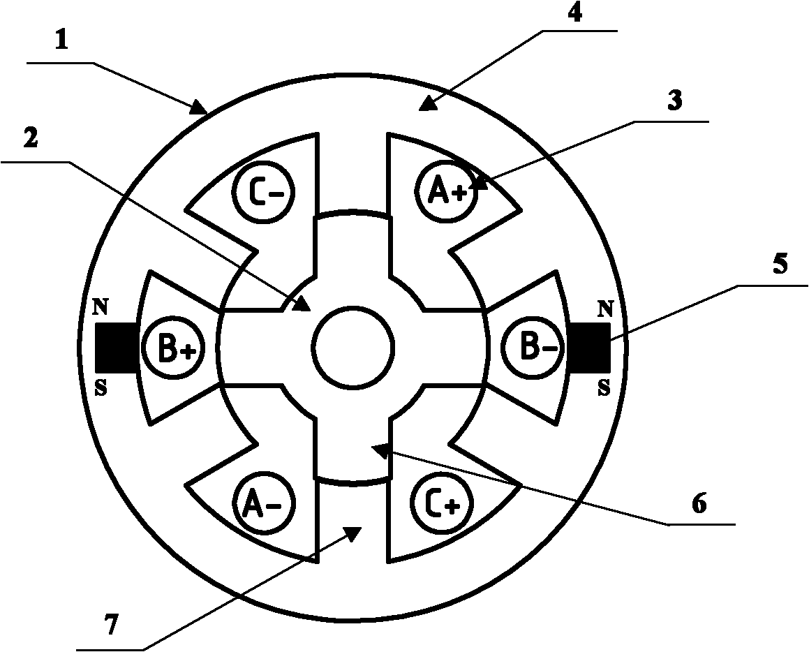
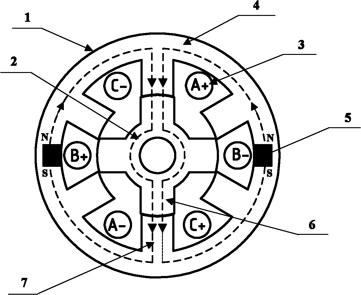
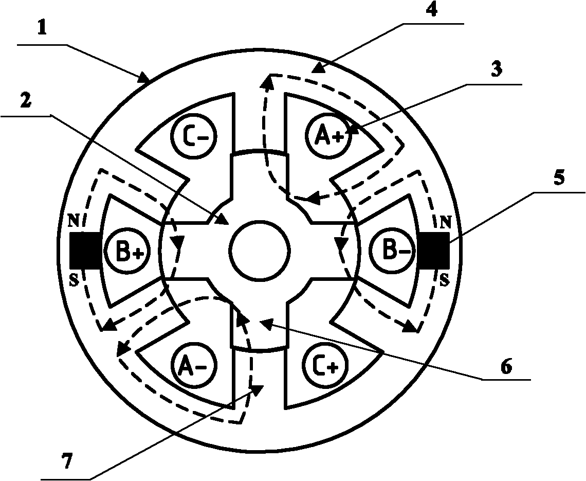
[0023] figure 1 Shown is a schematic structural diagram of a permanent magnet switched reluctance motor using distributed windings in the present invention. The motor includes a stator 1 and a rotor 2 sleeved inside the stator. Both the stator 1 and the rotor 2 are ring-shaped salient pole structures, and the inner ring of the stator 1 There are evenly distributed stator teeth 7 on the surface, and evenly distributed rotor teeth 6 on the outer ring surface of the rotor 2. There is a gap between the mutually nested stator core 4 and the rotor core 2, and the permanent magnet 5 is embedded in the stator core 4. The yoke, wherein: the stator 1 is wound with a three-phase armature winding 3 composed of a distributed structure, and there is only one winding coil between the slots of the adjacent stator teeth 7, and the coils that cross two stator slots are connected to fo...


PUM


Abstract

The invention discloses a permanent magnet switched reluctance motor employing a distributed winding. The motor comprises a stator and a rotor sleeved inside the stator, wherein the stator and the rotor have an annular salient pole structure; the surface of a stator inner ring is provided with uniformly distributed stator teeth; the surface of a rotor outer ring is provided with uniformly distributed rotor teeth; a gap is formed between mutually sleeved stator core and rotor core; a permanent magnet is embedded in a stator core yoke; the stator adopts a three-phase armature winding in a distributed structure; only one winding coil is arranged between adjacent stator tooth grooves; coils passing through two stator grooves are connected to form a one-phase winding; the three-phase windings are mutually induced and coupled; during work, two-phase windings are excited and electrified at any moment; and the output torque of interacted armature winding and permanent magnet is greater than independent excitation output torque of the armature winding. The invention solves the problem that the conventional switched reluctance motor winding has low utilization rate and low motor power density. The motor can be used as an electric motor and a generator.

Description

technical field [0001] The invention belongs to the field of motors and relates to a permanent magnet switched reluctance motor with distributed windings. Background technique [0002] The stator and rotor of the traditional switched reluctance motor adopt a salient pole structure, and the stator winding is generally a concentrated winding. By sequentially energizing the stator excitation winding, the stator pole and the rotor pole interact to generate torque. Since there are neither windings nor permanent magnets on the rotor, the structure of the motor is simple and the operation is reliable. However, this traditional switched reluctance motor has only one phase excitation at any time when it is working. In a switching cycle of the stator winding, at most only half of the cycle is used. In order to obtain a larger output torque and power, the size of the motor requires Relatively large, thereby reducing the performance volume ratio of the motor. [0003] In order to over...

Claims


Application Information

Patent Timeline
IPC IPC(8): H02K29/00H02K1/14H02K1/17H02K1/24
Inventor 高琳丁文梁得亮娄建勇杜锦华
Owner XI AN JIAOTONG UNIV
Why Eureka
Try Eureka