Dispensing device

A technology of a glue dispensing device and a glue injection device is applied in the field of dialyzers, which can solve the problems of low production efficiency and low product qualification rate.

Inactive Publication Date: 2011-05-04
贝恩医疗设备(广州)有限公司
View PDF5 Cites 12 Cited by
  • Summary
  • Abstract
  • Description
  • Claims
  • Application Information

AI Technical Summary

Problems solved by technology

[0003] In the prior art, the production of puncture needles is usually done manually. The needle is manually inserted into the needle holder, and then glued to fix the needle and the needle holder. The production efficiency is low and the product qualification rate is not high.

Method used


Image

  • Dispensing device
  • Dispensing device

Examples


Embodiment 1

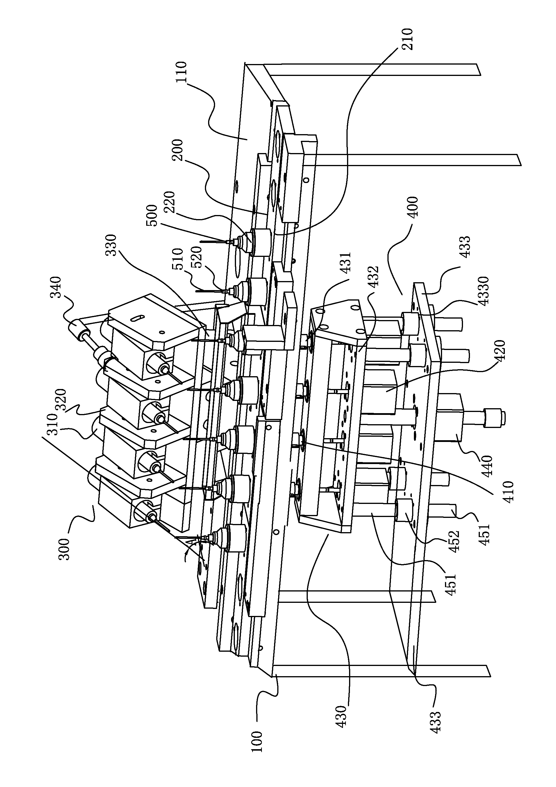
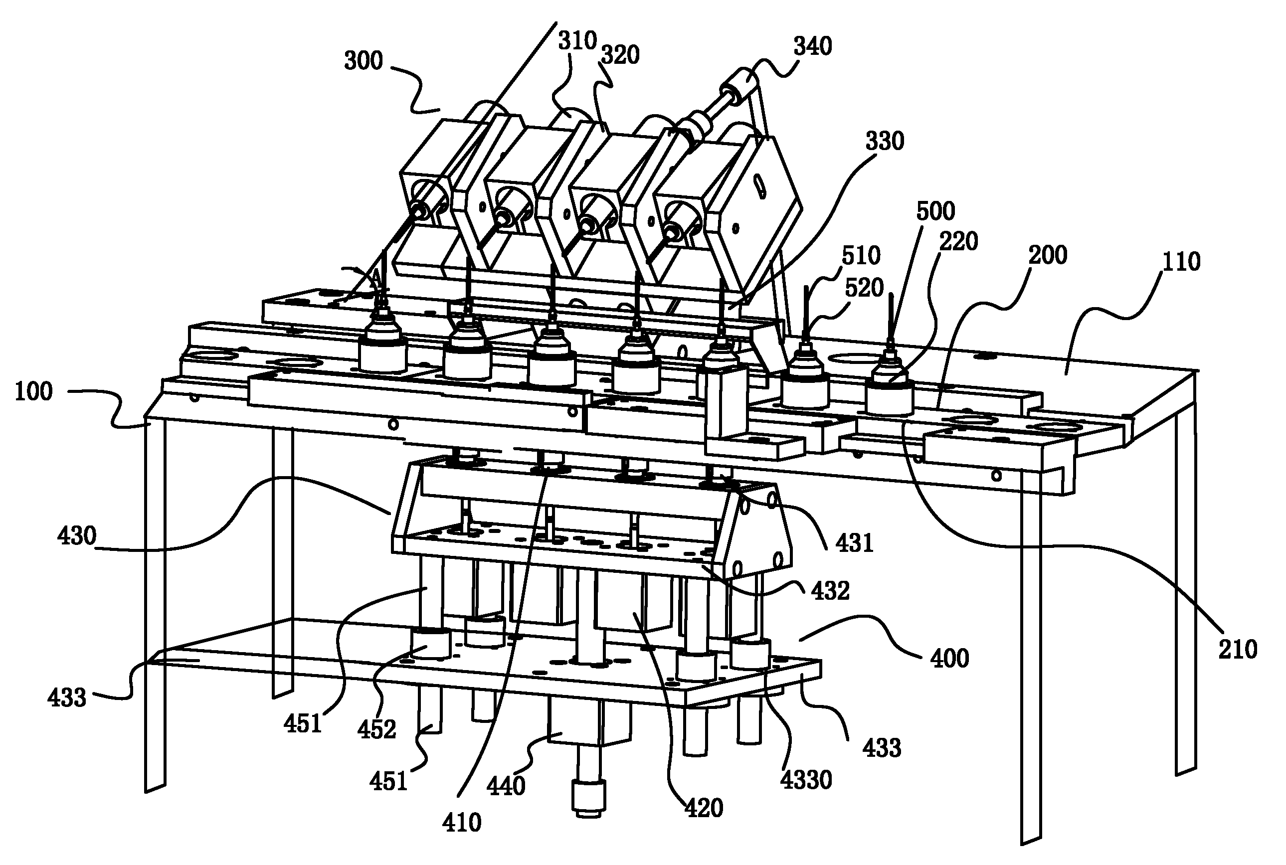
[0056] A dispensing device such as figure 1 As shown, a frame body 100, an automatic feeding device 200, a glue injection device 300, a rotating device 400 and a control device are provided.

[0057] The frame body 100 is used to carry the automatic feeding device 200, the glue injection device 300, and the rotating device 400. The automatic feeding device 200 transports the puncture needle 510 and the needle seat 520 that need to be glued to the corresponding position for glue injection. The delivered puncture needle 510 and needle base 520 are processed. During the glue injection process, the rotating device 400 rotates the automatic feeding device 200 so that the glue can be injected into the connection between the puncture needle 510 and the needle base 520 . The entire glue injection process is controlled by the control device to ensure the effective cooperation between the various parts.

[0058] The frame body 100 is provided with a substrate 110, the automatic feeding...

Embodiment 2

[0068] A dispensing device of the present invention, other mechanisms are the same as in Embodiment 1, the difference is that in this embodiment, the angle A between the axis where the glue injection tube 310 is located and the plane where the substrate 110 is located is 45°, not only The glue injection process is convenient and accurate, and the preparation is simple and convenient.


PUM


Abstract

The invention relates to a dispensing device provided with a rack body, an automatic feeding device, a gluing device, a rotating device and a controlling device, wherein the rack body is provided with a base plate; the automatic feeding device is arranged on the upper part of the base plate; the gluing device is fixed on the base plate; the rotating device is arranged on the lower part of the base plate; the automatic feeding device is provided with a material plate, a material support and a power mechanism; the gluing device is provided with a gluing tube, a gluing rack, a rack support and agluing cylinder; the rack support and the gluing cylinder are fixed to the base plate; the gluing rack is moveably arranged on the rack support; the gluing tube is arranged on the gluing rack; the gluing rack is moveably connected with the gluing cylinder; the rotating device is provided with a driving part and a motor; the driving part is arranged below the material support; the motor is provided with a motor shaft; and the driving part is connected with the motor. Through the dispensing device, a gluing needle is bound to a needle file for gluing so as to have high production efficiently and high product percent of pass.

Description

technical field [0001] The invention relates to the field of dialyzers, in particular to a glue dispensing device for producing puncture needles. Background technique [0002] Dialyzer, commonly known as artificial kidney, has been widely used clinically. By performing hemodialysis, the patient's life can be appropriately extended. A dialyzer usually includes a housing, a hollow fiber arranged in the housing, a blood inlet pipe, a blood outlet pipe, a dialysate outlet pipe and a dialysate inlet pipe arranged at both ends of the housing. During hemodialysis, blood flows into each hollow fiber from the blood inlet tube, and after being filtered by the hollow fiber tube, flows back to the blood vessel of the patient from the blood outlet tube, and at the same time, the dialysate enters the shell through the dialysate inlet tube outside the hollow fiber The flow direction of the dialysate is opposite to that of the blood flow. Under the action of the osmotic pressure and the p...

Claims


Application Information

Patent Timeline
Patent Type & Authority Applications(China)
IPC IPC(8): B05C5/00B05C11/10B05C13/02A61M25/18
Inventor 廖磊
Owner 贝恩医疗设备(广州)有限公司
Why Eureka
Try Eureka