Spherical parts batch plasma based ion injection method and apparatus thereof

An ion implantation device and plasma technology are applied in ion implantation plating, metal material coating process, coating and other directions, which can solve the problems of uneven implantation and the inability to achieve uniform processing effect of spherical parts, and achieve uniform processing effect, Improve the service life and prevent the effect of arcing

Inactive Publication Date: 2009-01-28
HARBIN INST OF TECH
View PDF1 Cites 12 Cited by
  • Summary
  • Abstract
  • Description
  • Claims
  • Application Information

AI Technical Summary

Problems solved by technology

[0003] The purpose of the present invention is to solve the problem that the existing plasma-based ion implantation device and method for rotating workpieces perform plasma-based ion implantation on spherical parts, which has uneven implantation and cannot achieve consistent processing effects for the same batch of spherical parts

Method used


Image

  • Spherical parts batch plasma based ion injection method and apparatus thereof
  • Spherical parts batch plasma based ion injection method and apparatus thereof
  • Spherical parts batch plasma based ion injection method and apparatus thereof

Examples


specific Embodiment approach 1

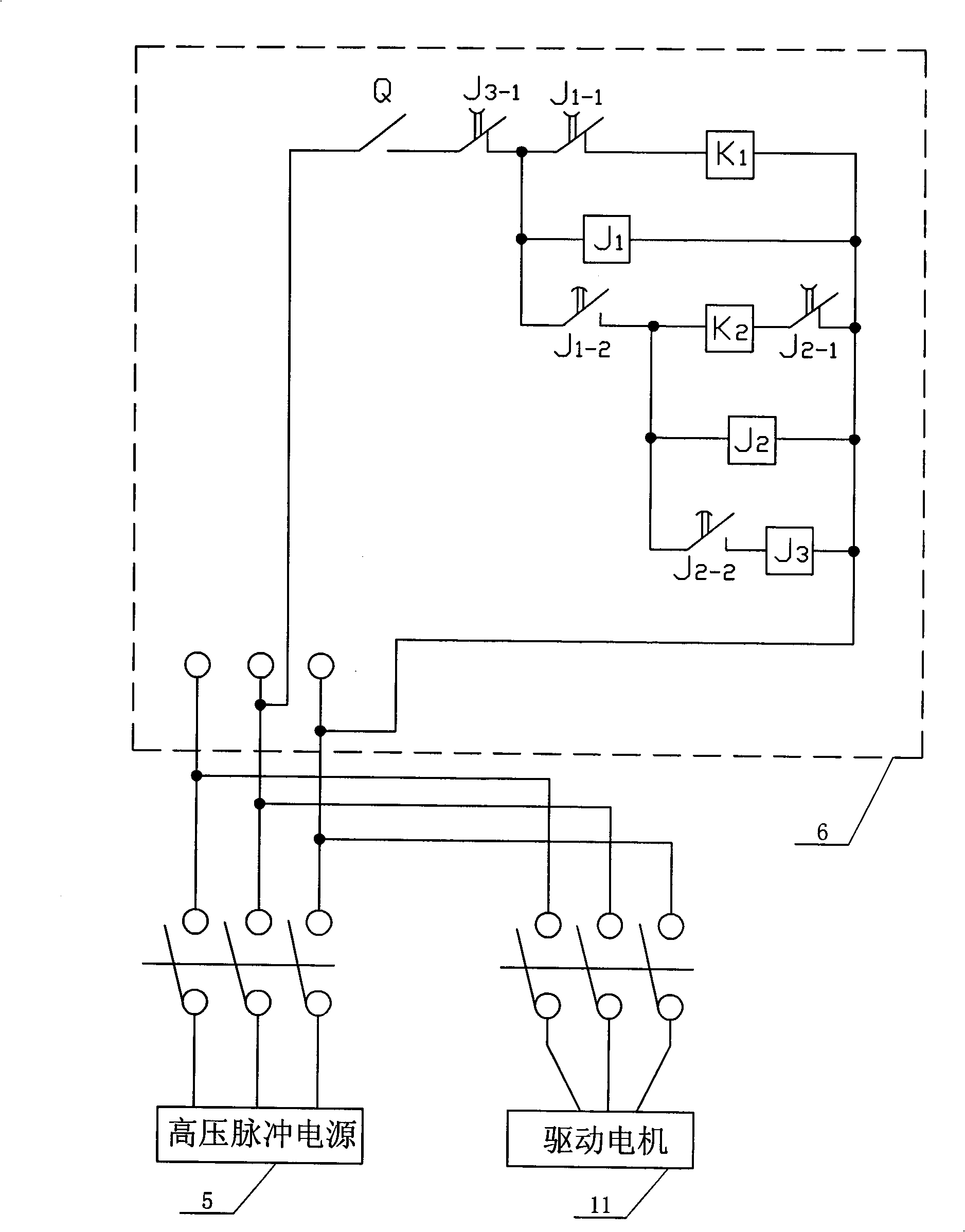
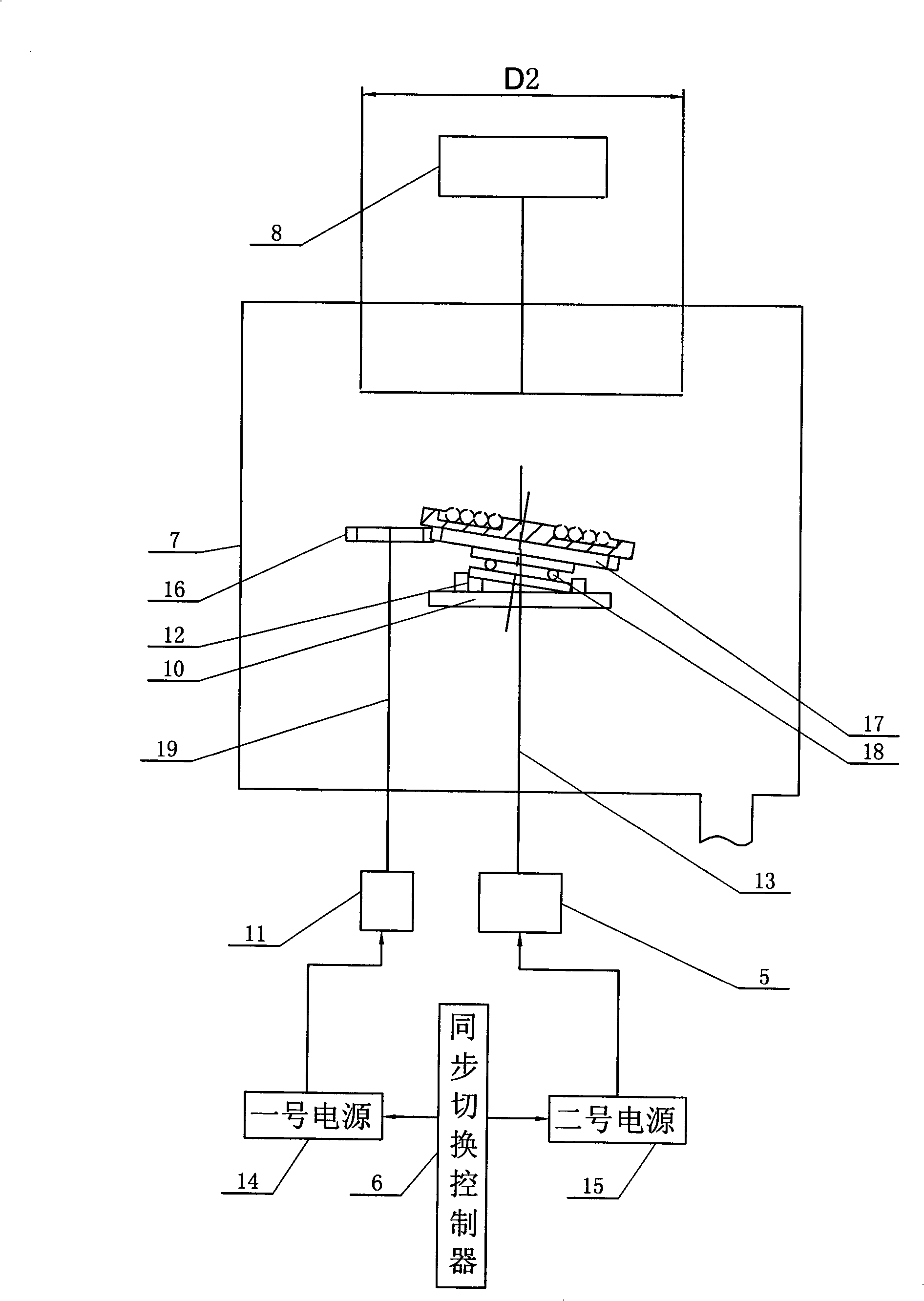
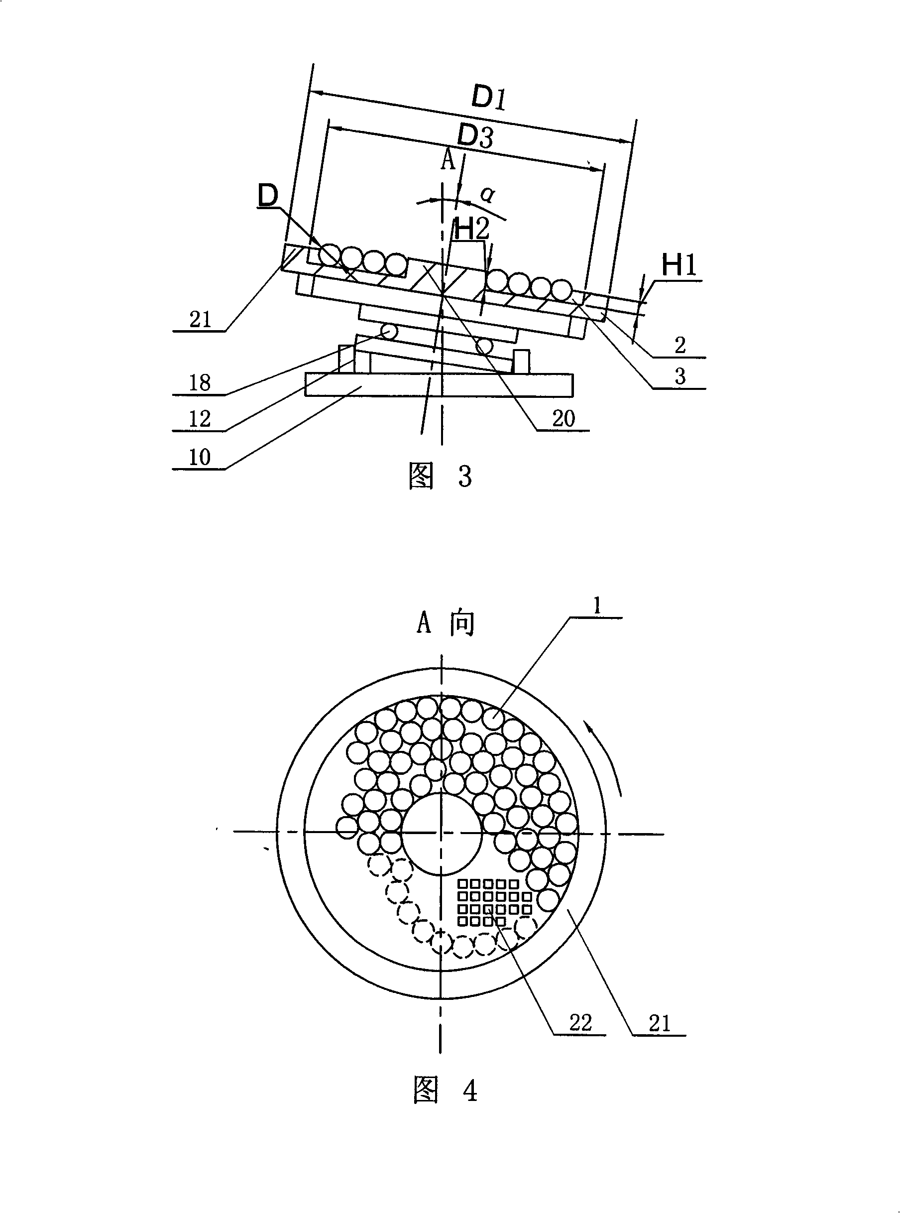
[0008] Specific implementation mode 1: Combination figure 2 4 illustrates this embodiment, the ion implantation method of this embodiment is completed as follows: a plurality of spherical parts 1 with the same diameter D are placed in the annular groove 3 of the inclined disc 2, the center of the inclined disc 2 The angle α between the axis and the vertical direction is 5°-30°, the rotation of the tilting disc 2 is controlled by the drive motor 11 and the transmission device, and the start and stop of the drive motor 11 and the high-voltage pulse power supply 5 are controlled by synchronous switching Controlled by the device 6, first apply a high-voltage pulse voltage to the spherical part 1, and perform plasma-based ion implantation on the surface of the spherical part 1. After the implantation time is 5-10 minutes, stop applying the high-voltage pulse voltage, and start the drive motor 11 at the same time to tilt the disc The rotation of 2 makes the part of the spherical part 1 ...

specific Embodiment approach 2

[0010] Embodiment 2: This embodiment will be described with reference to FIGS. 3 and 4. The diameter D of the spherical part 1 of this embodiment is 3-50 mm, and the surface ion implantation treatment can be performed on the spherical part 1 of different diameters. The other method steps are the same as in the first embodiment.

specific Embodiment approach 3

[0011] Specific embodiment three: this embodiment is described with reference to Figs. 3 and 4. The angle α between the central axis of the inclined disc 2 and the vertical direction of this embodiment is 5°-30°, which can ensure the surface of the spherical part 1 The ion implantation is uniform and consistent. The other method steps are the same as in the first embodiment.

[0012] Specific implementation manner 4: Combination figure 2 4 illustrates this embodiment. The maximum cross-sectional area of ​​the spherical part 1 placed in the annular groove 3 of the inclined disc 2 in this embodiment accounts for less than 3 / 4 of the bottom area of ​​the annular groove 3 of the inclined disc 2, which is conducive to Uniform ion implantation is performed on the surface of the spherical part 1. The other method steps are the same as in the first embodiment.


PUM

PropertyMeasurementUnit
diameteraaaaaaaaaa
diameteraaaaaaaaaa

Abstract

The invention discloses a spherical-component batch plasma-based ion implantation method and a device thereof, relating to a spherical-component plasma-based ion implantation method and a device thereof and aiming at the problem that the plasma-based ion implantation of spherical components which is carried out to spherical components by adopting a device and a method of rotary-workpiece plasma-based ion implantation is uneven and can not realize the uniform treatment effect of the spherical components of the same batch. The method of the invention comprises the following steps: the spherical components are put in a circular groove of an oblique round plate, the rotation of which is controlled by a driving motor and a gear; the rotation of the driving motor is stopped first, a high-voltage pulse power source is turned on, and after time delay by the high-voltage pulse power source, plasma-based ion implantation is carried out to the spherical components; and the starting and stopping of the driving motor and the high-voltage pulse power source are kept synchronously switched. The device of the invention comprises: a synchronous switching controller provides the driving motor and the high-voltage pulse power source with power by No. 1 and No.2 power sources; an output shaft of the driving motor is fixedly provided with a driving gear which is meshed with a driven gear. The device and the method can uniformly implant the surface irons of the spherical components.

Description

Technical field [0001] The invention relates to a plasma-based ion implantation method and device for spherical parts, and belongs to the technical field of plasma-based ion implantation. Background technique [0002] Plasma-based ion implantation technology can achieve low-temperature surface modification of precision parts. Its characteristic is that it does not change the dimensional accuracy of the processed parts, and the temperature can be controlled at room temperature or slightly higher than room temperature, and can be used for all parts in a plasma environment. The surface is implanted at the same time, so this technology can realize batch processing. The basic principle of this technology is to form a plasma space around the workpiece. When a negative high voltage pulse is applied to the workpiece, the plasma is affected by the electric field on the workpiece to form a positive ion sheath around the workpiece. The electric field force is injected into the surface of th...

Claims


Application Information

Patent Timeline
Patent Type & Authority Applications(China)
IPC IPC(8): C23C14/32
Inventor 马欣新唐光泽
Owner HARBIN INST OF TECH
Why Eureka
Try Eureka