
Double-arm four-wheel polling robot mechanism

A technology of inspection robot and arm mechanism, which is applied in the field of mobile robots, can solve the problems of difficult application of ultra-high voltage transmission line inspection operations, limited ability to overcome obstacles, poor safety protection, etc., to achieve easy climbing of large-angle lines and reduce derailment Dangerous, walking ability effect

Active Publication Date: 2012-07-25
SHENYANG INST OF AUTOMATION - CHINESE ACAD OF SCI +1
View PDF0 Cites 0 Cited by
  • Summary
  • Abstract
  • Description
  • Claims
  • Application Information

AI Technical Summary

Problems solved by technology

These mechanisms have complex structure, heavy weight, limited ability to overcome obstacles and are not easy to control. They need to adjust the center of mass when they overcome obstacles, have small working space, small climbing angle, and poor safety protection when walking. Therefore, it is difficult to apply to actual ultra-high voltage power transmission. line inspection

Method used


Image

  • Double-arm four-wheel polling robot mechanism
  • Double-arm four-wheel polling robot mechanism
  • Double-arm four-wheel polling robot mechanism

Examples


Embodiment 1

[0037] Embodiment 1 (the front and rear arm mechanisms are fixed symmetrically on both sides of the casing, and the distance between the two arm mechanisms is fixed.)

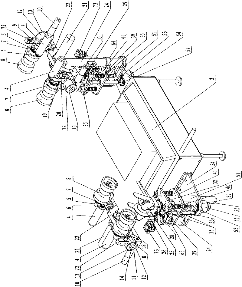
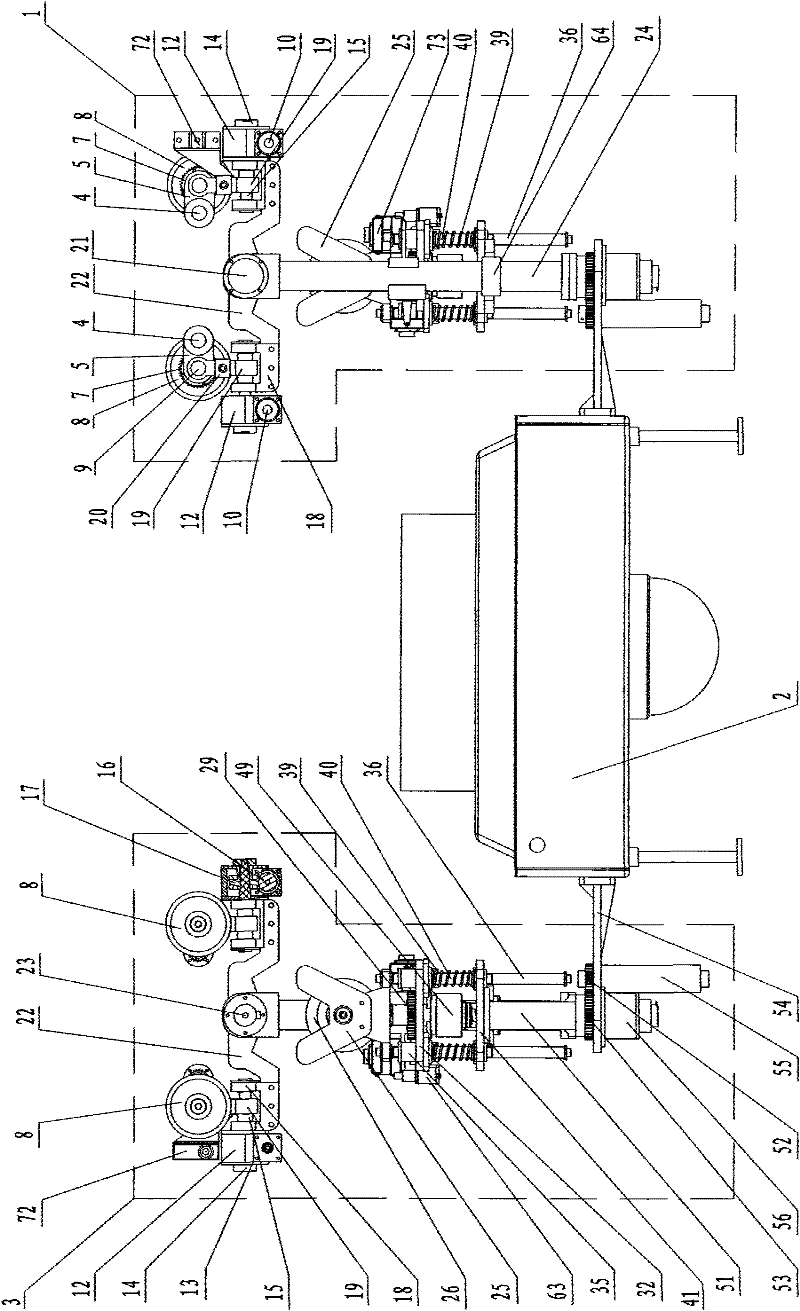
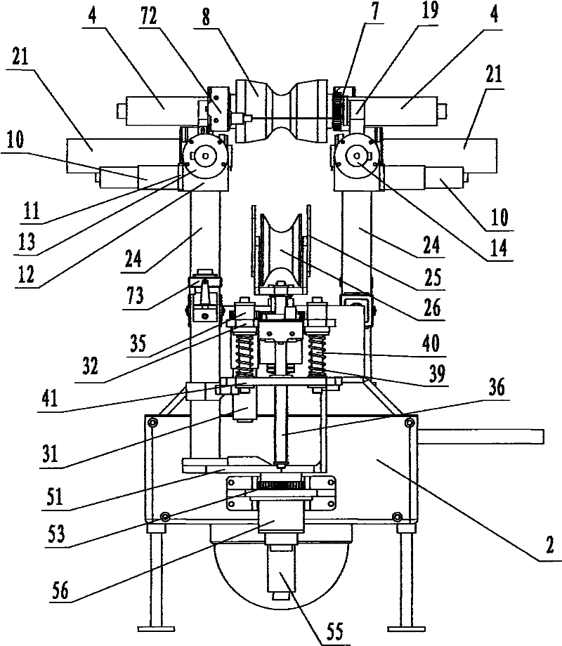
[0038] Such as Figure 1~3 As shown, the present invention is used for inspection operation on the overhead transmission line, including the front arm mechanism 1, the box body 2 and the rear arm mechanism 3, the front and rear arm structures 1 and 3 have the same structure, and are symmetrically installed on the box body 2 sides. Each arm mechanism includes two or more sets of walking mechanisms, a turning mechanism with the same number as the running mechanisms, a set of pitching mechanisms, one or more sets of clamping mechanisms and support arms 24, and the walking mechanisms of this embodiment are two groups, That is, the front traveling mechanism and the rear traveling mechanism, and the number of turning mechanisms are also two groups, that is, the front turning mechanism and the rear turning mechanism,...

Embodiment 2

[0060] Embodiment 2 (the distance between the front and rear arm mechanisms is adjustable through the transmission of the lead screw and the slider nut)

[0061] Such as Figure 15 As shown, the difference between this embodiment and Embodiment 1 is that the first and second motors 80, 83 are provided on the casing 2, and the output shafts of the two motors are respectively connected with the second and third motors installed on the casing 2. Leading screw 81,84, on the second and third leading screw 81,84, threadedly be connected with first, second slide block nut 82,85 respectively, front and rear arm mechanism 1,3 and second, one slide block nut 85, 82 is connected, the rotation of the second and first motors 83 and 80 is driven by the thread transmission of the third and second lead screws 84 and 81 and the second and first slider nuts 85 and 82 to drive the front and rear arm mechanisms 1 and 3 to reciprocate Move to adjust the distance between the two arm mechanisms. T...

Embodiment 3

[0062] Embodiment 3 (the distance between the front and rear arm mechanisms is adjustable through the transmission of the gear and the rack)

[0063] Such as Figure 16 As shown, the difference between this embodiment and Embodiment 1 is that: the casing 2 is provided with a third motor 89, the output shaft of the third motor 89 is connected with a gear 87, and the front and rear arm mechanisms 1, 3 are respectively connected There are first and second tooth racks 86,88 meshing with gear 87, and the first and second tooth racks 86,88 are set equally; the rotation of the third motor 89 is output by the gear 87 and the first and second tooth racks 86,88. The transmission drives the front and rear arm mechanisms 1 and 3 to reciprocate to adjust the distance between the two arm mechanisms. The third motor 89 works, the driving gear 87 rotates, and the gear 87 drives the first and second racks 86, 88 to move inward or outward through the engagement transmission with the first and ...


PUM


Abstract

The invention relates to a mobile robot, in particular to a double-arm four-wheel polling robot mechanism comprising a box body, a front arm mechanism and a rear arm mechanism, wherein the front arm mechanism and the rear arm mechanism are of the same structure and are respectively installed on the box body; each arm mechanism comprises travelling mechanisms, turnover mechanisms, an elevating gear, a clamping mechanism and a supporting arm, wherein one end of the supporting arm is connected with the box body, and the other end of the supporting arm is hinged with the elevating gear the two ends of which are respectively provided with the front turnover mechanism and the rear turnover mechanism; the front travelling mechanism and the rear travelling mechanism which can be turned over to the vertical state from the horizontal state are respectively connected to the output end of the front turnover mechanism and the output end of the rear turnover mechanism; the front travelling mechanism, the rear travelling mechanism, the front turnover mechanism and the rear turnover mechanism are linked with the elevating gear; and the clamping mechanism which is installed on the supporting arm and can clamp earth wires by moving up and down is arranged just below the front travelling mechanism and the rear travelling mechanism. The robot mechanism provided by the invention has the advantagesof good safety protection performance, strong crawling and obstacle-detouring capability, large working space, wide application range and the like.

Description

technical field [0001] The invention relates to a mobile robot, in particular to a dual-arm and four-wheel inspection robot mechanism. Background technique [0002] The transmission line is an extremely important part of the power system. In order to ensure its safe and stable operation, regular inspections are required. The methods currently used mainly include manual inspection and helicopter inspection. Manual inspections are inefficient, labor-intensive, and dangerous; helicopter inspections are costly and the quality of inspections is easily affected by the climate. Therefore, it is necessary to develop a robot that can carry communication and inspection equipment to replace manual automatic inspection of transmission lines to improve efficiency and ensure the safe operation of transmission lines. In the existing ultra-high voltage transmission line inspection robot mechanism, most of them adopt the composite mobile mechanism composed of wheeled mobile and composite l...

Claims


Application Information

Patent Timeline
Patent Type & Authority Patents(China)
IPC IPC(8): B25J5/00
Inventor 王洪光王智敏房立金张望英谢春雷倪孟华何立波宋彩珠章贤煜
Owner SHENYANG INST OF AUTOMATION - CHINESE ACAD OF SCI
Learn More