Direct drive type hoist with boosting caliper brake

A caliper brake and booster technology, which is applied to lifts, lifting equipment in mines, electromechanical devices, etc., can solve problems such as easy rollover of the car, difficulty in ensuring the working air gap of the motor, and difficulty in braking the hoist. Achieve the effect of reducing the size of the installation base, reliable operation, and reducing the size of the cross section

Inactive Publication Date: 2011-05-04
HENAN POLYTECHNIC UNIV
View PDF1 Cites 28 Cited by
  • Summary
  • Abstract
  • Description
  • Claims
  • Application Information

AI Technical Summary

Problems solved by technology

[0006] The technical problem to be solved by the present invention is to minimize the influence of the inherent normal attraction on the performance of the direct-drive hoist, the difficulty of braking the hoist, the difficulty in ensuring the working air g

Method used


Image

  • Direct drive type hoist with boosting caliper brake
  • Direct drive type hoist with boosting caliper brake
  • Direct drive type hoist with boosting caliper brake

Examples


Embodiment 1

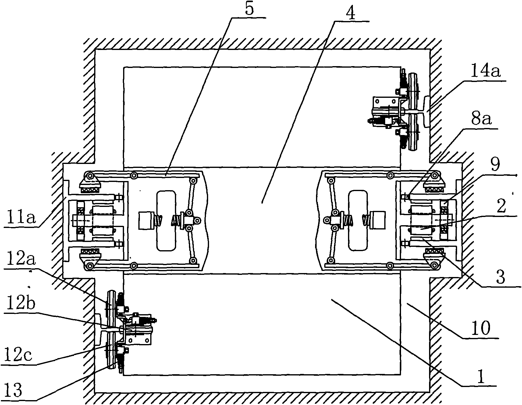
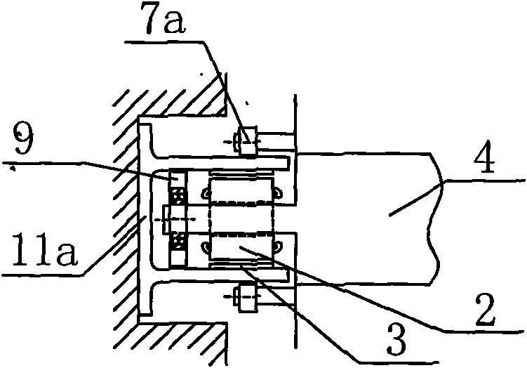
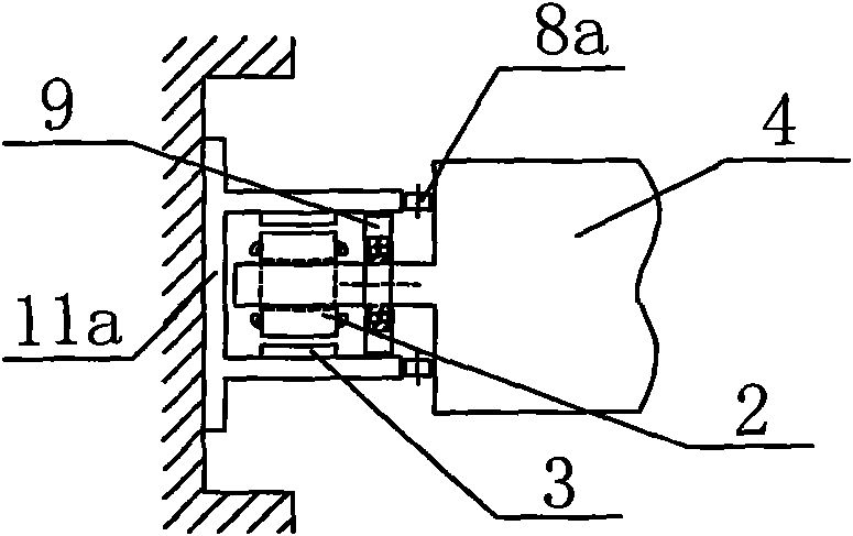
[0045] like figure 1 9 options for direct drive hoists with booster caliper brakes are shown, figure 1 (A) is the overall sectional schematic diagram of described direct-drive hoist, figure 1 (B~I) are the direct drive hoist and figure 1 (A) Partial cross-sectional schematic diagrams of different schemes adopted on the motor working air gap multi-wheel positioning mechanism.

[0046] Below to figure 1 (A) is taken as an example to explain in detail.

[0047] like figure 1 As shown in (A), a direct-drive hoist with a booster caliper brake includes a vertical shaft 10, a car 1, a booster caliper brake 5, a car frame 4, and a permanent magnet linear motor for lifting , safety gear, and positioning mechanism, and provide the power supply of the motor mover, car 1, and booster caliper brake 5 through the power supply cable fixed on the inner wall of the vertical shaft 10, the power supply rail contact or non-contact mode.

[0048] The driving source of the direct drive hoist ...

Embodiment 2

[0063] like image 3 As shown in the direct-drive hoist with booster caliper brake, the positioning mechanism is only provided with a motor working air gap multi-wheel positioning mechanism. Other structures are the same as those in Embodiment 1 figure 1 (A).

[0064] In addition, various motor working air gap multi-wheel alignment mechanisms described in Embodiment 1, such as figure 1 (B~I), be applicable to embodiment 2 equally.

Embodiment 3

[0066] like Figure 4 As shown, a direct-drive hoist with a booster caliper brake, the booster caliper brake 5 is installed on the diagonal position of the car 1 or the side extension beam of the car frame, and acts on the braking T-type Track I 14b. Other structures are the same as those in Embodiment 1 figure 1 (A).

[0067] In addition, various motor working air gap multi-wheel positioning mechanisms described in Embodiment 1, such as figure 1 (B~I), be applicable to embodiment 3 equally.


PUM


Abstract

The invention discloses a direct drive type hoist with a boosting caliper brake. The hoist comprises a vertical shaft, a cage, a cage rack, the boosting caliper brake, a safety gear and a positioning mechanism, wherein a fixed beam is arranged on an inner wall mounting base of the vertical shaft; a hoisting permanent magnet linear motor is arranged between the fixed beam and the cage rack; the boosting caliper brake is arranged on the cage rack or the cage; and a brake boosting mechanism and a drive boosting mechanism are arranged on the brake. Compared with those of the conventional identical or similar brakes, the specification, dimension and weight of a push mechanism such as springs are greatly reduced, the braking force and the driving force are increased by one to two orders of magnitude compared with those of common boost-free brakes, and the cage accurately and reliably brakes. The positioning mechanism is arranged between the inner wall of the shaft and the cage. By adopting the scheme of the positioning mechanism and the hoisting linear motor with a slender structure, the variation of a working air gap of the motor is controlled within an engineering allowed band, normal attraction force in unit length is greatly reduced, stress concentration is avoided, and the cage stably operates.

Description

technical field [0001] The invention belongs to the field of cordless lifting, in particular to a direct-drive hoist with booster caliper brakes. Background technique [0002] The hoist or elevator is an important transportation link in mines and various buildings. In the common hoisting system, the hoisting method is well known. The structure used by the hoist is that the mechanical room is installed on the upper part of the hoist, and the rotating motor drives the roller, winding The wire rope on the drum is connected to the car at one end and to a counterweight at the other end. However, for ultra-high buildings and ultra-deep mines with a large number of people and heavy loads, a high level of traffic handling capacity is required, and hoists occupy a large amount of building space and low transport capacity is a serious problem. [0003] In order to overcome the above-mentioned problems, a linear motor hoist that does not require wire ropes and a separate machine room ...

Claims


Application Information

Patent Timeline
IPC IPC(8): B66B9/00B66B17/00B66B11/04B66B11/00B66B17/02B66B15/08B66B7/04B66B5/18H02K41/02
Inventor 汪旭东封海潮许宝玉许孝卓袁世鹰上官璇峰张高峰
Owner HENAN POLYTECHNIC UNIV
Why Eureka
Try Eureka