
Gasification method of carbon-containing solid raw material and used reactor

A gasification reactor and oxidation reaction technology, which is used in the manufacture of combustible gas, petroleum industry, energy input, etc., can solve the problems of unsafe operation of downstream devices and equipment, easily damaged waste boilers, and high temperature of synthesis gas discharged from the gasifier. , to achieve the effect of ensuring long-term operation, ensuring continuity and ensuring stability

Active Publication Date: 2014-07-09
CHINA PETROCHEMICAL CORP +2
View PDF4 Cites 0 Cited by
  • Summary
  • Abstract
  • Description
  • Claims
  • Application Information

AI Technical Summary

Problems solved by technology

However, it is found in production practice that chilling to 900°C cannot guarantee that all molten fly ash will become solid
[0006] 3. The chilled synthetic gas contains a large amount of solid fly ash, which has the following adverse effects on the operation of downstream equipment: first, it will severely corrode downstream equipment and easily damage the waste boiler; second, it is easy to damage the waste boiler. Dust accumulation on the heating surface affects the waste heat recovery effect of the synthesis gas process, causing the steam output to drop or the temperature cannot reach the design value, and the temperature of the synthesis gas discharged from the gasifier is too high, which brings unsafe factors to the operation of downstream devices and equipment ; Third, in order to prevent the internal structure and blockage of the waste boiler coil, the waste boiler can only adopt the water pipe structure, that is, the water / steam goes in the pipe, resulting in the size of the waste boiler and the corresponding pressure shell being too large

Method used


Image

  • Gasification method of carbon-containing solid raw material and used reactor
  • Gasification method of carbon-containing solid raw material and used reactor

Examples


Embodiment Construction

[0026] The present invention will be further described in detail below in conjunction with the accompanying drawings and embodiments.

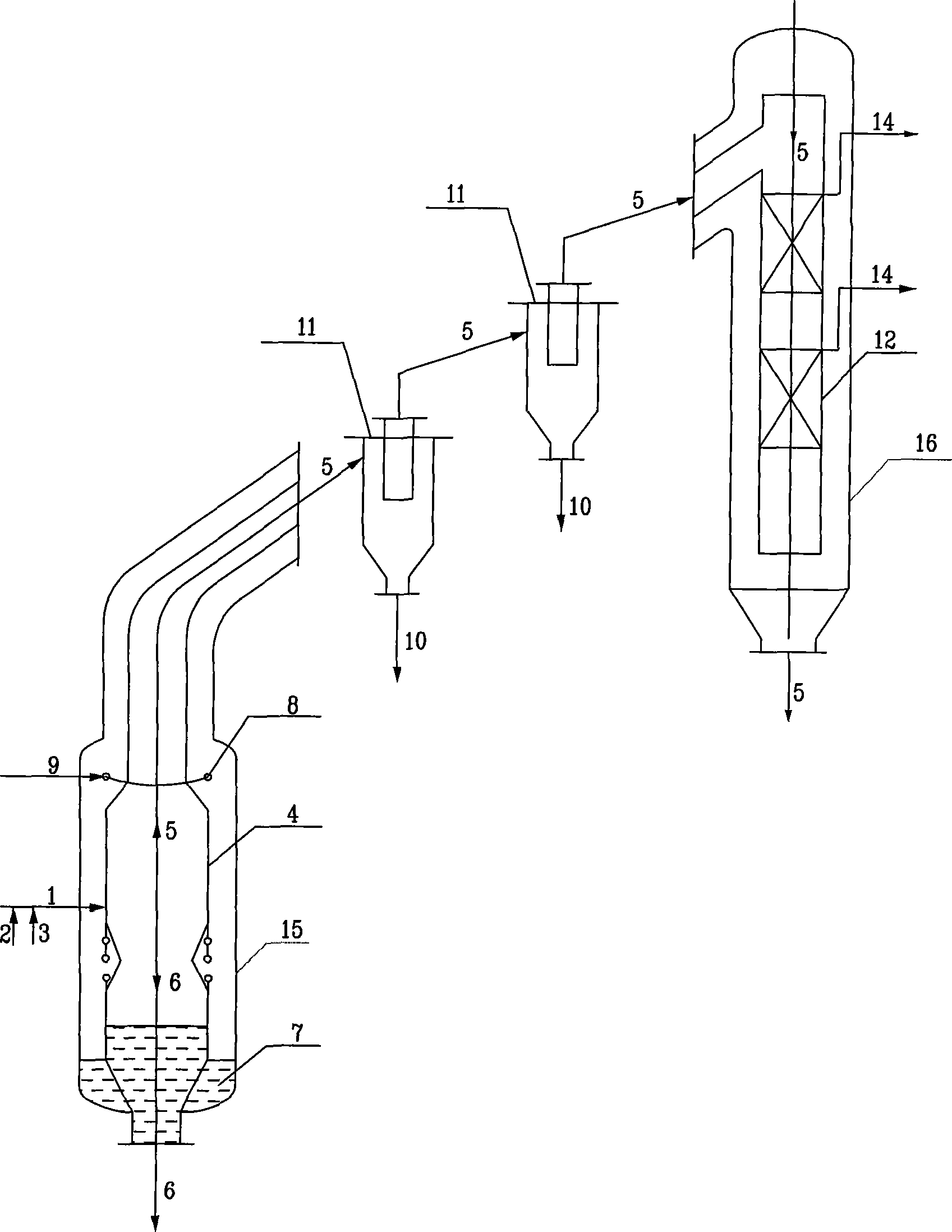
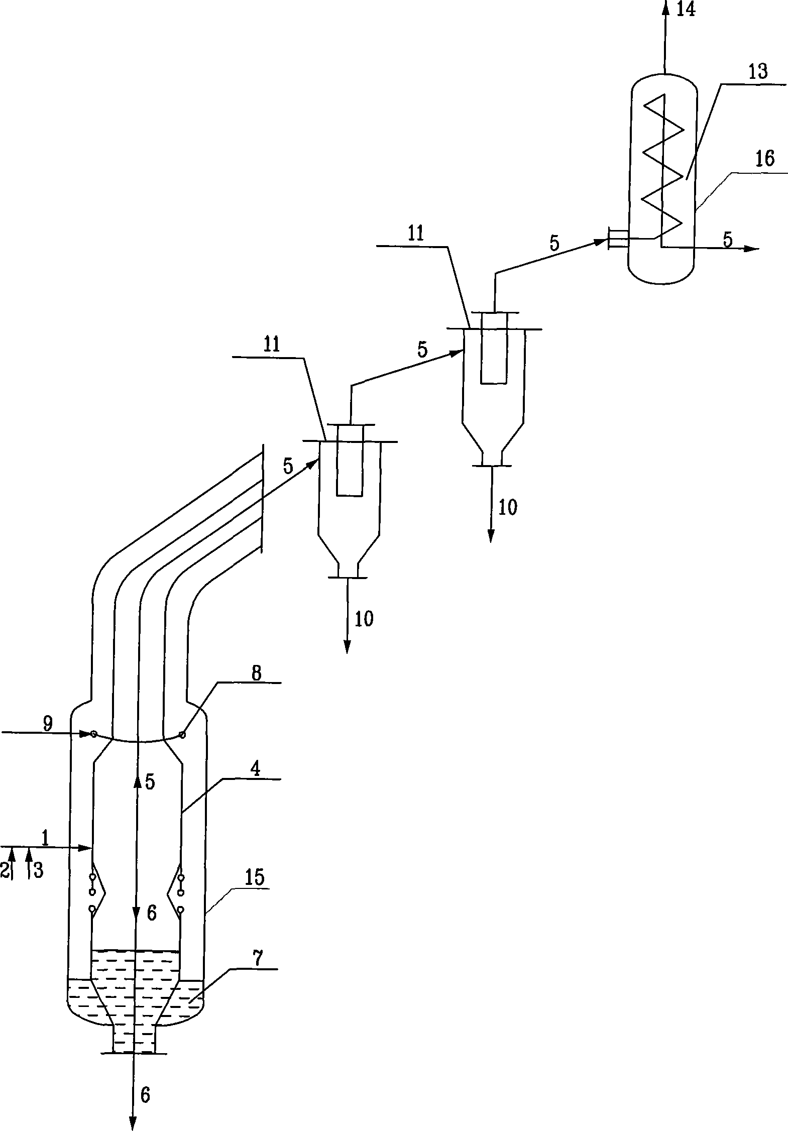
[0027] Such as figure 1 and figure 2 As shown, the gasification reactor for the carbonaceous solid raw material includes a reactor unit 4, a slag pool 7 and a quenching zone, a dust removal unit 11 and a waste pot unit; wherein, the reactor unit 4, the slag pool 7 and the quenching zone It is arranged in the first pressure vessel shell 15 , the waste boiler unit is set in the second pressure vessel shell 16 , and the dust removal unit is located downstream of the first pressure vessel shell 15 and upstream of the second pressure vessel shell 16 .

[0028] Such as figure 1 As shown, a carbon-containing solid feedstock 2 and an oxygen-containing gas 3 are fed into a reactor unit 4 through a burner 1 . In the reactor unit 4, a carbon-containing solid feedstock 2 is subjected to a non-catalytic partial oxidation reaction with an oxygen-contain...


PUM


Abstract

The invention relates to a gasification method of a carbon-containing solid raw material and a used reactor. The gasification method is characterized by comprising the following steps of: reacting the carbon-containing solid raw material with oxygen in a reactor unit so as to generate synthesis gas, wherein ash flows downwards into a slag pool at the lower end of a gasification reactor in the slag form under the action of gravity force; allowing high-temperature synthesis gas which entrains molten ash residues to rise to a chill zone in the gasification reactor, injecting steam or / and water into the chill zone by using chilling equipment and chilling the high-temperature synthesis gas so as to freeze the molten ash residues entrained in the high-temperature synthesis gas into solid dust; introducing the synthesis gas which entrains the chilled solid dust into a dust removing unit so as to remove dust entrained in the synthesis gas; and introducing the synthesis gas into a waste boiler unit and generating steam by using process waste heat of the synthesis gas. The reactor provided by the invention isolates a gasification furnace from the waste boiler unit through respective shell and the dust removing unit is arranged between the gasification furnace and the waste boiler unit. The equipment has low wear rate and can run for a long time.

Description

technical field [0001] The invention relates to a gasification method of carbon-containing solid raw materials and a used reactor. Background technique [0002] The gasification of the existing carbon-containing solid feedstock is usually implemented in an extended gasification reactor vessel, and the gasification reactor includes a gasifier unit, a slag pool and a boiler unit downstream of the gasifier unit; The gasifier unit is coaxially provided with a cooling channel, through which the dusty hot gas product of the gasifier unit, that is, syngas, is discharged from the reactor; the downstream of the gasifier unit is provided with an existing The structure of the gasifier (take the Shell gasifier as an example, other technologies are similar to the structure of the Shell gasifier) ​​is shown in the accompanying drawings. It adopts the overall gasifier structure, and the reactor unit, slag pool and the waste pot unit downstream of the reactor unit are combined in a pressur...

Claims


Application Information

Patent Timeline
Patent Type & Authority Patents(China)
IPC IPC(8): C10J3/86C10J3/84
CPCY02P20/129
Inventor 亢万忠章晨晖李晓黎郭文元张炜
Owner CHINA PETROCHEMICAL CORP
Learn More