Device for cooling an exhaust gas flow emitting from a particulate filter

A particle filter and exhaust gas flow technology, applied in the field of exhaust gas flow devices, can solve problems such as troublesome structure, and achieve the effect of improving clamping effect and compact structure

Inactive Publication Date: 2011-05-04
DEERE & CO
View PDF10 Cites 1 Cited by
  • Summary
  • Abstract
  • Description
  • Claims
  • Application Information

AI Technical Summary

Problems solved by technology

Due to the electrical control of the air pump, the known device is relatively complex in construction

Method used


Image

  • Device for cooling an exhaust gas flow emitting from a particulate filter
  • Device for cooling an exhaust gas flow emitting from a particulate filter
  • Device for cooling an exhaust gas flow emitting from a particulate filter

Examples


Embodiment Construction

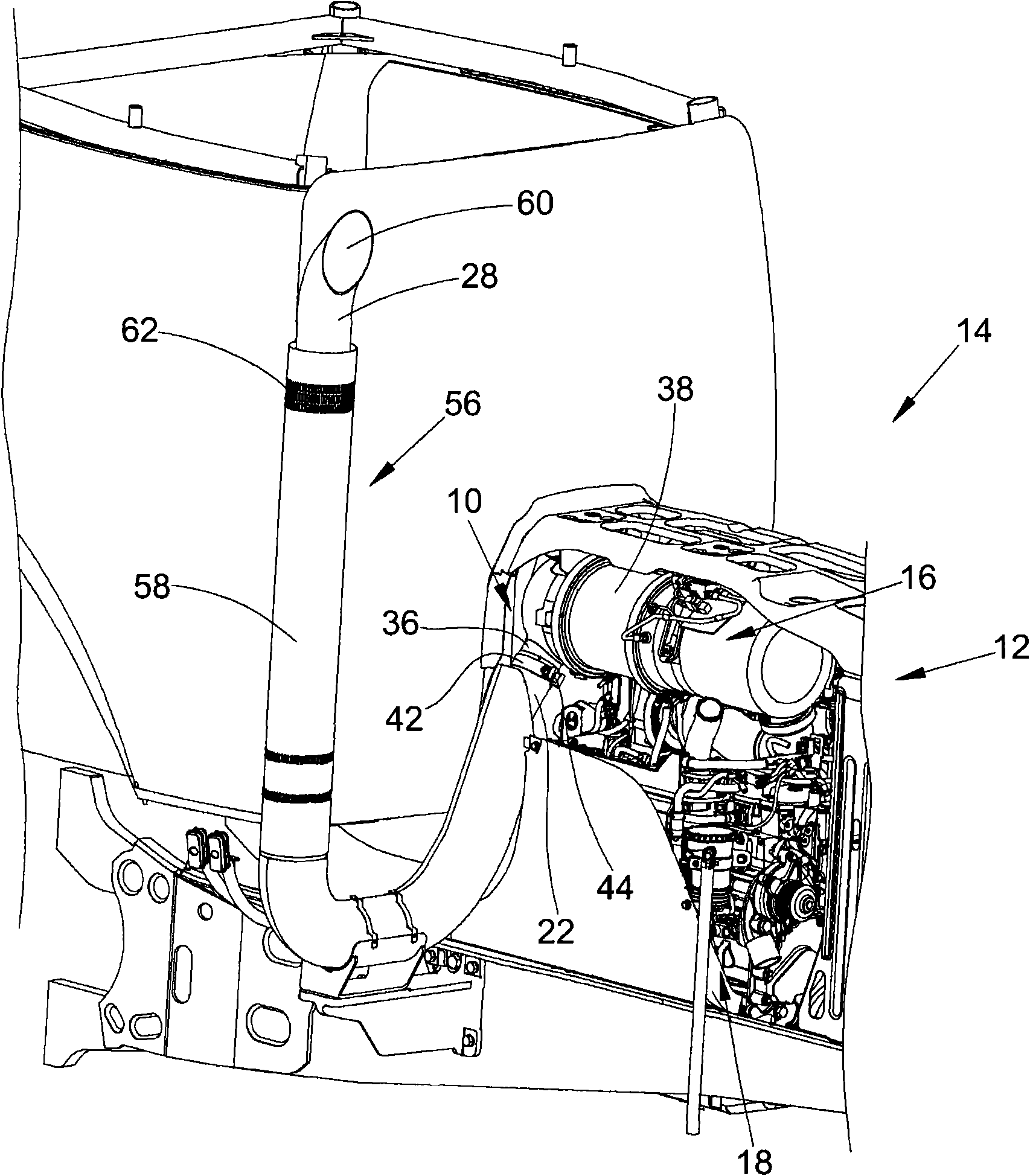
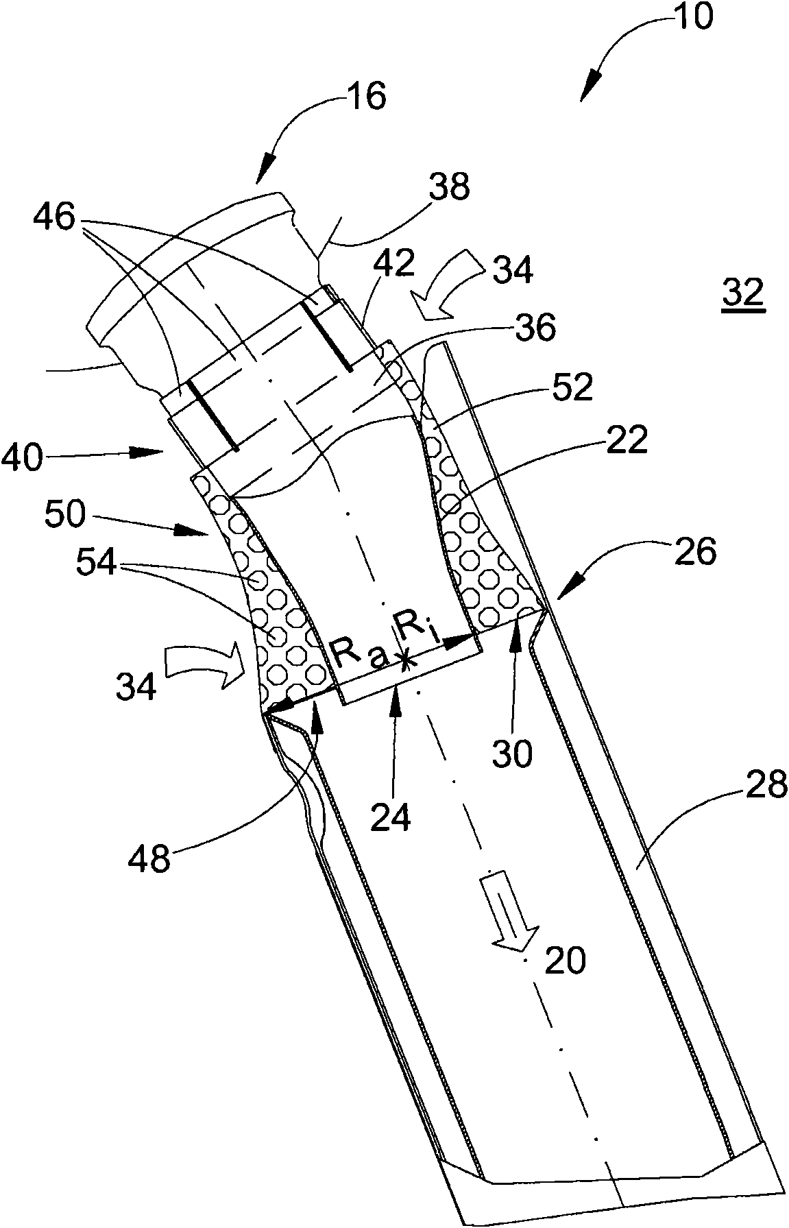
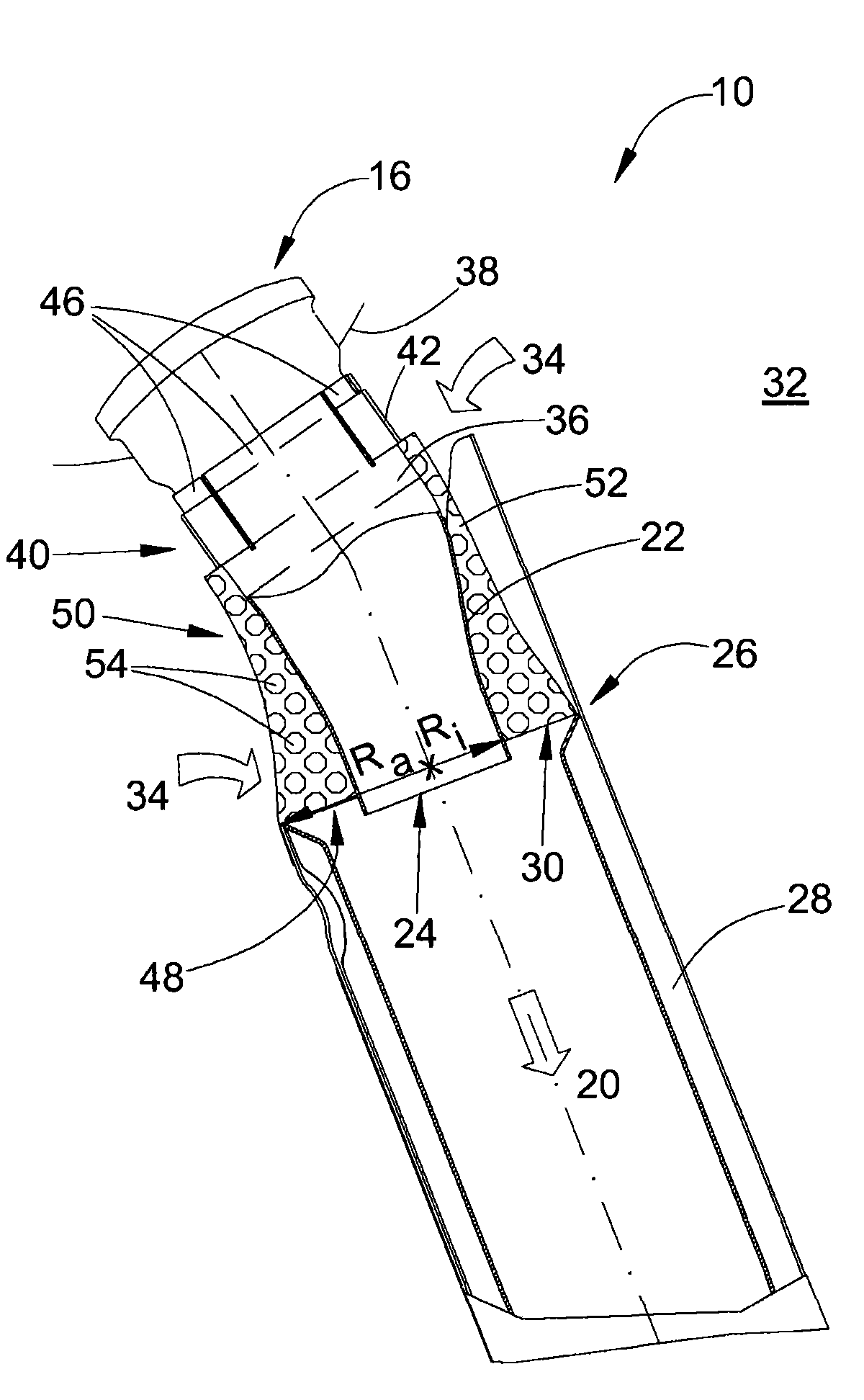
[0024] figure 1 Shows a general perspective view of an exemplary embodiment of a device according to the invention for cooling an exhaust gas stream exiting a soot filter, mounted on an agricultural vehicle in the form of a tractor, wherein figure 2 A detailed view of the device according to the invention is shown in longitudinal section.

[0025] The soot filter 16 which is arranged together with the device 10 according to the invention in the engine compartment 12 of the agricultural vehicle 14 is formed in the shown case by a conventional wall flow filter, wherein the air produced by the diesel engine 18 of the agricultural vehicle 14 Engine exhaust passes through porous filter walls made of ceramic or metallic materials. The soot particles contained in the engine exhaust gas deposit here not only on the surface of the soot filter 16 but also within its filter wall. Since the back pressure of the exhaust gas increases with the degree of clogging of the filter wall, in or...


PUM


Abstract

The present invention relates to a device (10) for cooling an exhaust gas steam (20) discharged from a soot particle filter (16) which is provided with an outlet connection pipe (22) that is used for feeding out the exhaust gas steam (20), wherein the outlet connection pipe (22) is provided with a pipe opening part (24) which shrinks along the direction of the exhaust gas steam (20). The pipe opening part extends into an open end (26) of an adjacent exhaust gas pipe (28) so a negative pressure relatively to an environment (32) can be generated in a suction part (30) formed between the outlet connection pipe (22) and the exhaust gas pipe (28) when the exhaust gas steam (20) passes through.

Description

technical field [0001] The invention relates to a device for cooling an exhaust gas flow exiting a soot filter. Background technique [0002] Exhaust gas standards issued by the European Union provide for the gradual reduction of soot particles produced by diesel engines and emitted to the environment through the engine exhaust. Soot particulate emissions are limited by the use of soot particulate filters, usually so-called wall flow filters, in which engine exhaust gases enter porous filter walls made of ceramic or metallic materials. The soot particles contained in the engine exhaust gas are deposited not only on the surface of the filter wall but also inside it, so that the exhaust gas back pressure increases with the increasing degree of clogging of the filter wall. For the regeneration of the soot filter, therefore, the deposited soot particles are burned at regular intervals, for which the temperature of the engine exhaust gas is sometimes raised to more than 500° C.,...

Claims


Application Information

Patent Timeline
Patent Type & Authority Applications(China)
IPC IPC(8): F01N3/05F01N3/023
CPCF01N3/021F01N3/05F01N13/082F01N2250/10F01N2270/02F01N2470/30F01N2590/08Y02T10/12
Inventor R·布鲁内特S·D·奥克斯纳
Owner DEERE & CO
Why Eureka
Try Eureka