Pressure relief device

A pressure relief device and air control technology, applied in wind power generation, wind turbines, machines/engines, etc., can solve problems such as burnout, inability to reduce wind pressure, and the threat of wind turbines

Active Publication Date: 2011-05-04
UNITED SHIP DESIGN & DEVELOPMENT CENTER
View PDF0 Cites 8 Cited by
  • Summary
  • Abstract
  • Description
  • Claims
  • Application Information

AI Technical Summary

Problems solved by technology

[0002] With the emergence of oil and other energy crises, the current countries are all devoting themselves to the research and development of new alternative energy sources, such as wind energy, solar energy, geothermal energy, tidal energy, etc. Among them, wind energy is widely used in various countries due to its characteristics of zero pollution and low construction cost. favor, see figure 1 As shown, it is a known wind power generator, which includes a tower 1, a generator body 2 is connected to the top of the tower 1, and a blade group 3 is connected to the front end of the generator body 2, thereby, wind energy Drive the blade group 3 to rotate around the shaft, drive the generator body 2 to generate electricity, and then convert the wind energy into electrical energy for use. The wind speed will cause the blade group 3 to rotate too fast, causing the generator body 2 to run excessively and burn out. Therefore, the existing wind generators have automatic braking devices. When the wind speed exceeds a predetermined value, they will automatically slow down or stop running. The protection effect is achieved, but the automatic braking device cannot reduce the wind pressure on the blade group 3. Excessive wind speed will still cause damage such as blade breakage of the wind generator, especially in areas prone to typhoons, often blowing Strong winds up to level 10 and above, and the wind direction is unpredictable, will pose a serious threat to the wind turbine. Therefore, how to develop a pressure relief device to automatically start when the wind speed is too high, so as to reduce the overall pressure of the wind turbine. It is necessary to withstand the wind pressure

Method used


Image

  • Pressure relief device
  • Pressure relief device
  • Pressure relief device

Examples


Embodiment Construction

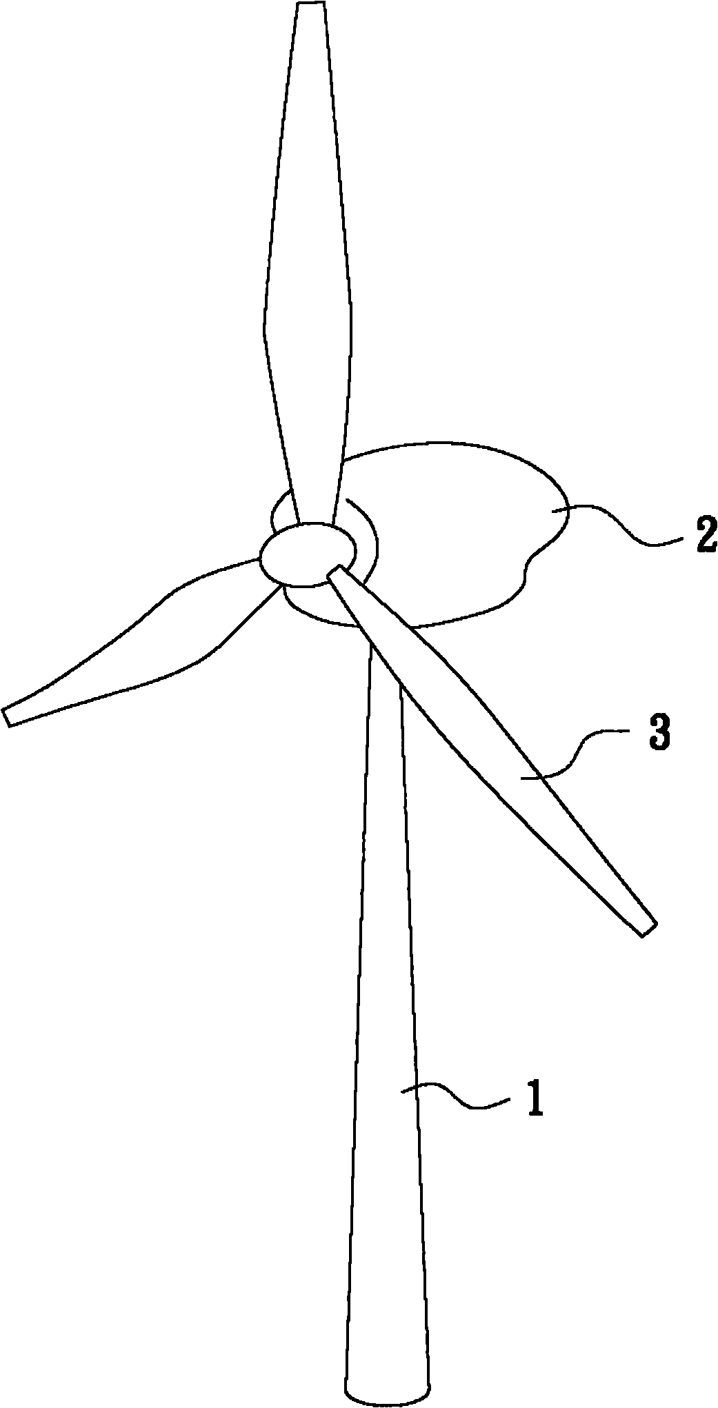
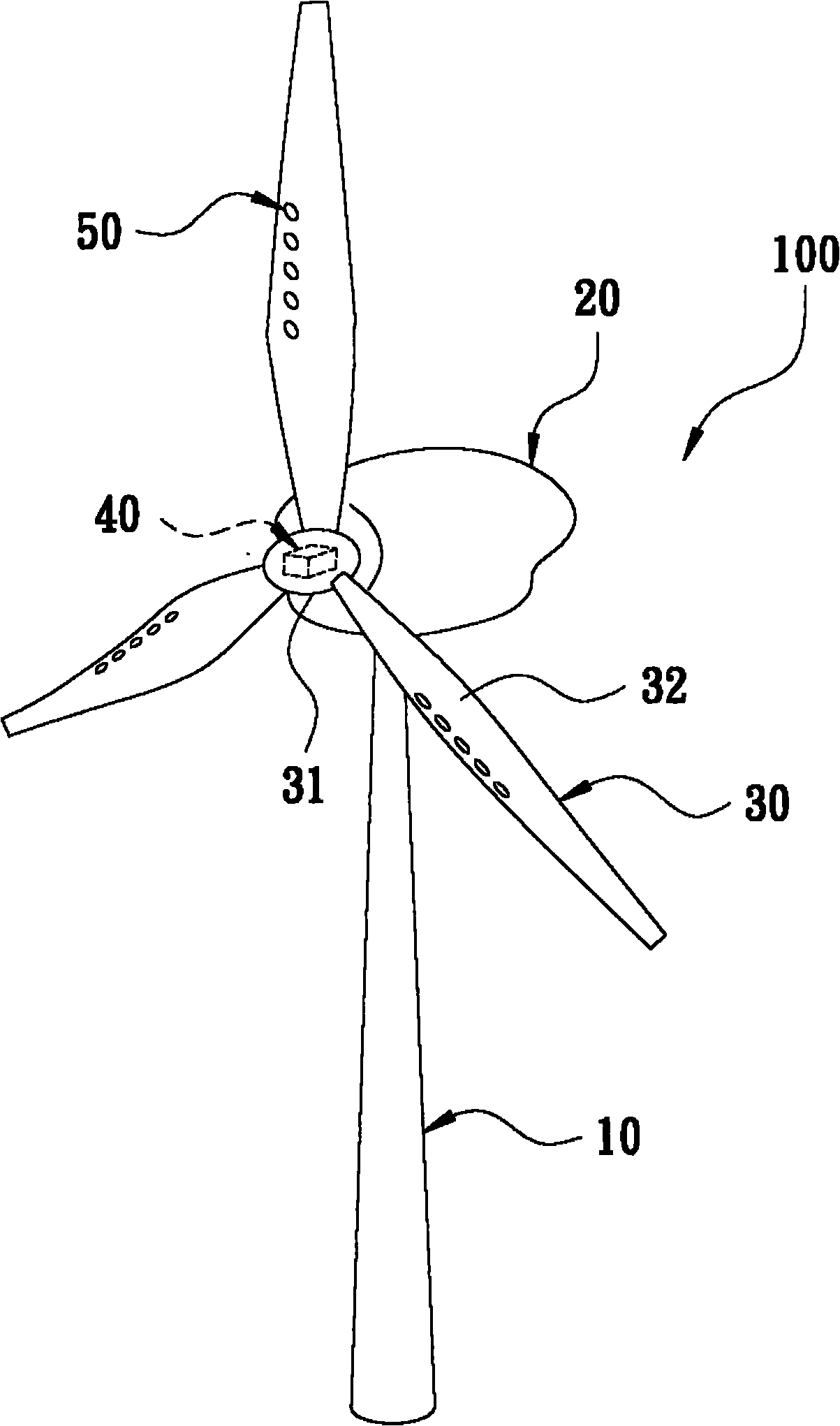
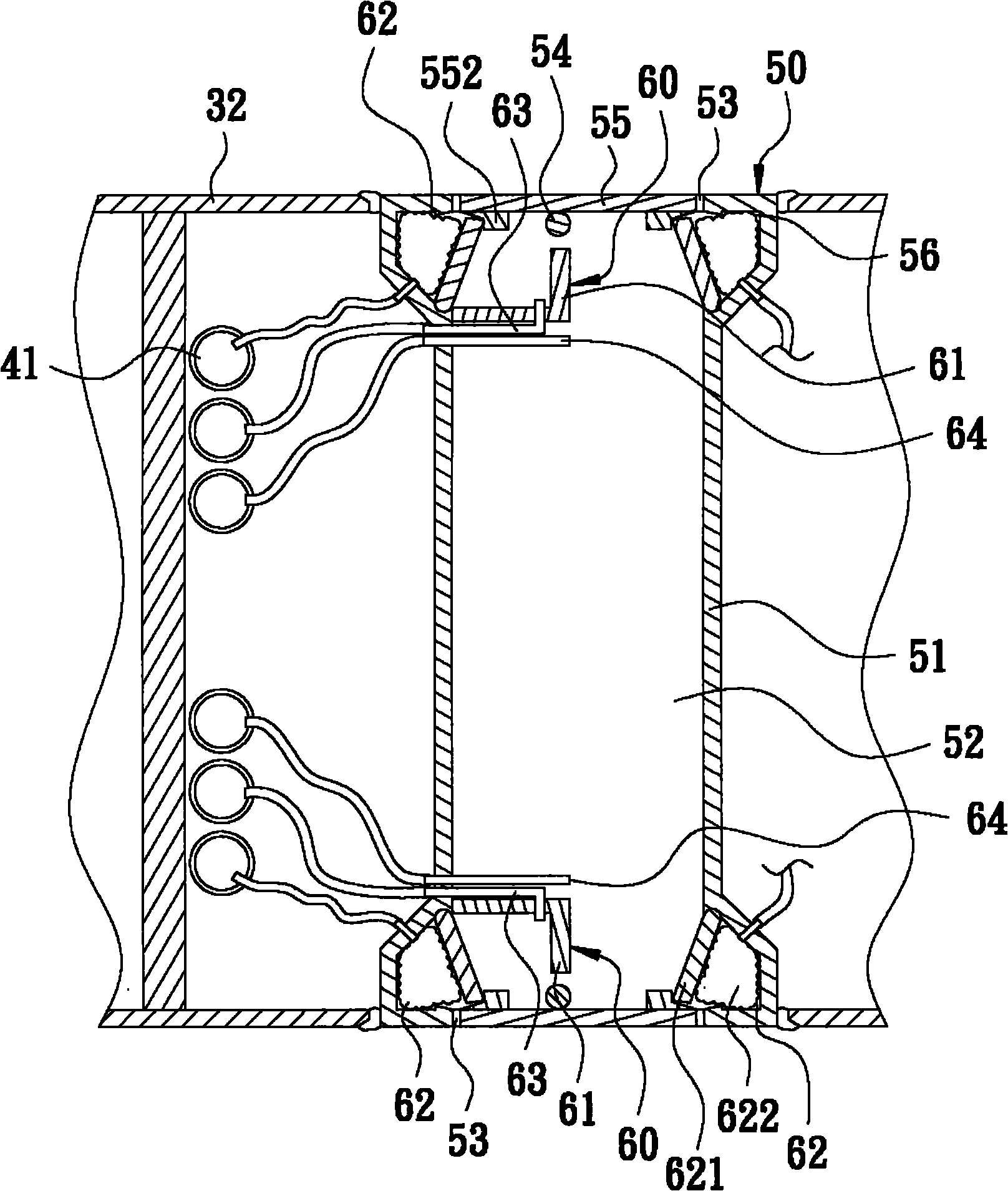
[0013] see figure 2 and image 3 As shown, it is a perspective view and a partially enlarged cross-sectional view of a preferred embodiment of the present invention. The wind generator 100 includes a tower 10, a generator body 20 located at the top of the tower 10, and a generator body 20 arranged on the generator body 20. The blade set 30 at the front end, an air control device 40 arranged in the shaft cover 31 of the blade set 30, and several pressure relief devices 50 distributed on the blades 32 of the blade set 30, wherein the pressure relief device 50 contains:

[0014] A main body 51 is provided with a flow channel 52 through both ends, and is formed with two flow channel openings 53, and the inside of these flow channel openings 53 are as Figure 4 As shown, a cover plate 55 is eccentrically pivoted through a pivot shaft 54, and the cover plate 55 can be divided into two blocks 551 centered on the pivot shaft 54, and each of these blocks 551 is symmetrically provide...


PUM


Abstract

The invention relates to a pressure relief device which comprises a main body, wherein at least one runner with two through ends is arranged in the main body and provided with at least two runner openings, the runner openings are internally and transversely pivoted with a cover plate respectively; and in addition, the pressure relief device is provided with an air control unit respectively in positions in the runner, close to the cover plates, and the air control units are connected to an air control device. Therefore, the air control device can drive the air control units to control the opening and the closing of the cover plates and further control the opening and the closing of the runner.

Description

technical field [0001] The present invention relates to a pressure relief device. Background technique [0002] With the emergence of oil and other energy crises, the current countries are all devoting themselves to the research and development of new alternative energy sources, such as wind energy, solar energy, geothermal energy, tidal energy, etc. Among them, wind energy is widely used in various countries due to its characteristics of zero pollution and low construction cost. favor, see figure 1 As shown, it is a known wind power generator, which includes a tower 1, a generator body 2 is connected to the top of the tower 1, and a blade group 3 is connected to the front end of the generator body 2, thereby, wind energy Drive the blade group 3 to rotate around the shaft, drive the generator body 2 to generate electricity, and then convert the wind energy into electrical energy for use. The wind speed will cause the blade group 3 to rotate too fast, causing the generator ...

Claims


Application Information

Patent Timeline
Patent Type & Authority Applications(China)
IPC IPC(8): F03D1/06F03D7/02
CPCY02E10/72
Inventor 吴兆诚何智男
Owner UNITED SHIP DESIGN & DEVELOPMENT CENTER
Why Eureka
Try Eureka