Conductive coating structure for lighting device

A lighting device and conductive package technology, which is applied to lighting devices, components of lighting devices, lighting and heating equipment, etc., can solve problems such as poor conductive performance, inability to effectively improve speed, and affect the service life of lighting devices. Achieve the effect of improving yield and stability

Inactive Publication Date: 2013-06-05
LIANG MENG PLASTIC SHARE
View PDF2 Cites 0 Cited by
  • Summary
  • Abstract
  • Description
  • Claims
  • Application Information

AI Technical Summary

Problems solved by technology

[0004] However, this lighting device still has the following problems in actual use: since its light-emitting module is installed in the accommodation space, there is a large amount of air in the accommodation space, and when the conductive circuit is exposed to the air, it is very easy to Combining with oxygen molecules in the air to form oxides, it is easy to cause poor electrical conductivity, and even seriously affect the service life of the overall lighting device
In addition, it is formed by combining and installing each component one by one, which not only consumes a lot of labor costs for assembly, but also cannot effectively improve the speed of the production process, thereby greatly reducing its practicability and economic benefits

Method used


Image

  • Conductive coating structure for lighting device
  • Conductive coating structure for lighting device
  • Conductive coating structure for lighting device

Examples


Embodiment Construction

[0030] The detailed description and technical content of the present invention are described below with accompanying drawings, but the attached drawings are only for reference and description, and are not intended to limit the present invention.

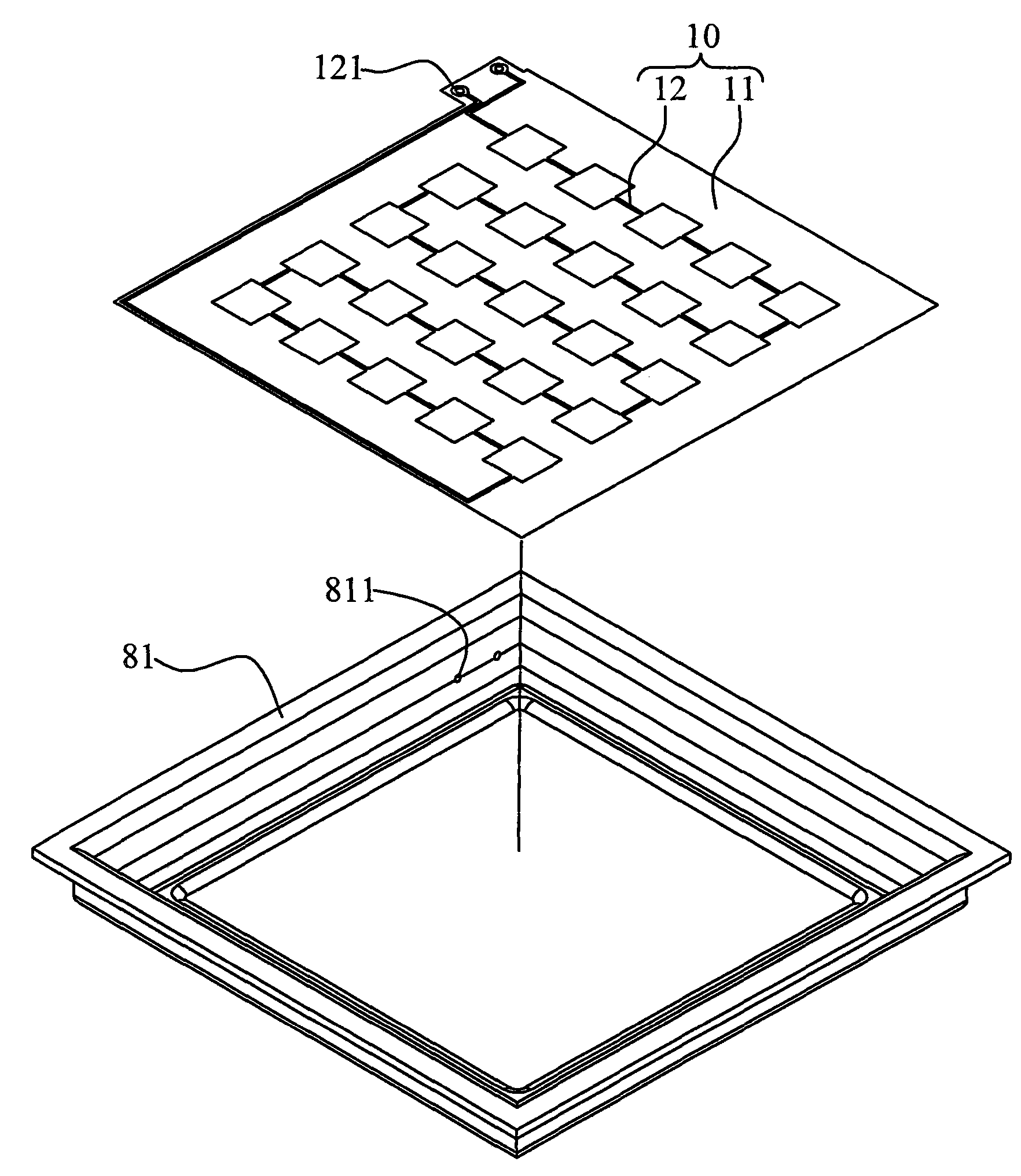
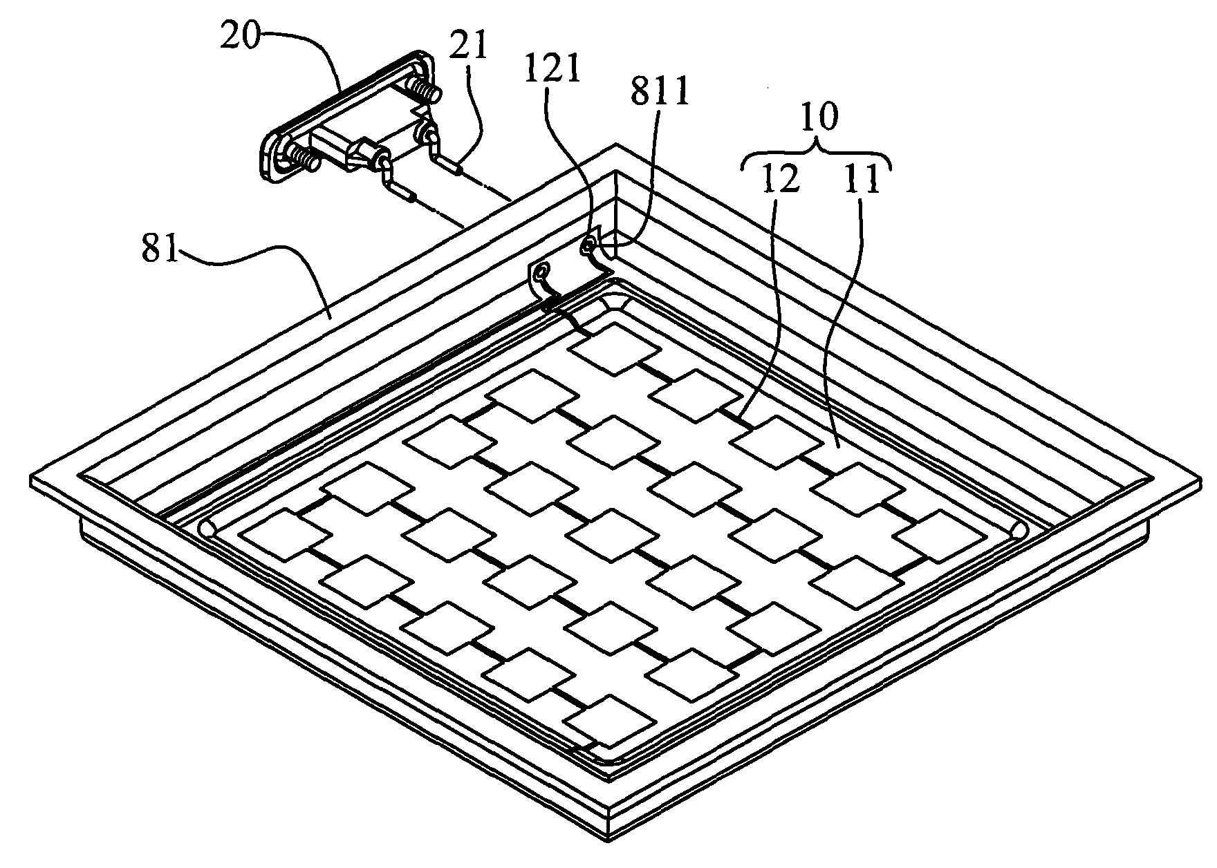
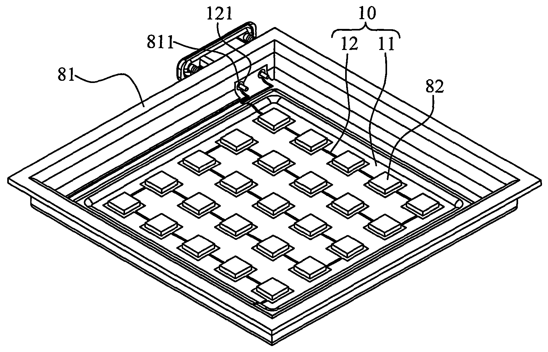
[0031] Please refer to Figure 1 to Figure 4 As shown, the present invention provides a conductive coating structure of a lighting device. The lighting device 8 includes a metal socket 81 and a plurality of light-emitting components 82. The metal socket 81 in this embodiment is a box with an open end. The light-emitting The component 82 can be in the form of a bare LED or a lens-packaged LED. The conductive covering structure includes a conductive circuit 10 , an electrical connector 20 , a light-transmitting body 30 and a lampshade 40 .

[0032] The conductive circuit 10 is composed of an insulating layer 11 and a copper foil circuit layer 12 arranged above the insulating layer 11. The insulating layer 11 corresponds to the inner su...


PUM


Abstract

The invention provides a conductive coating structure for a lighting device. The lighting device comprises a metal bearing base and two or more than two light-emitting components. The conductive coating structure comprises a conducting circuit, an electric connector, a light-transmitting body and a lamp shade, wherein the conducting circuit is arranged on the surface of the metal bearing base andis electrically connected with the light-emitting components; the electric connector is fixed on the metal bearing base and is in electrically conducting connection with the conducting circuit; the light-transmitting body is coated outside the conducting circuit and the electric connector to be formed in a solidification mode; and the lamp shade is coated outside the electric connector and the light-transmitting body to be formed in a solidification mode, so that the influence caused by moisture and steam can be effectively avoided, oxidation resistance is improved, and the service life is prolonged.

Description

technical field [0001] The present invention relates to a conductive coating structure, in particular to a conductive coating structure of an illuminating device. Background technique [0002] Light-emitting diodes (LEDs) in light-emitting components have been widely and widely used in indoor or outdoor lighting devices because of their good brightness, long life and power saving, which determines the advantages and disadvantages of these lighting devices Failure, always can not escape the various factors that electrical components are damaged by the influence of temperature, humidity, oxidation, etc.; [0003] The known lighting device mainly includes a lampshade, a light-emitting module and a light-transmitting mirror, wherein the light-transmitting mirror is fixed on one side of the lampshade, and an accommodating space is formed between the light-transmitting mirror and the lampshade, and the light-emitting module is installed in the accommodating space , and it is comp...

Claims


Application Information

Patent Timeline
Patent Type & Authority Patents(China)
IPC IPC(8): F21V23/00F21V23/06F21V3/00F21V13/00H01L33/00F21Y101/02
Inventor 赖光柱
Owner LIANG MENG PLASTIC SHARE
Why Eureka
Try Eureka