Planar MR Safety Cables for Biopotential Measurements

A magnetic resonance and safety technology, applied in the direction of measuring magnetic variables, measuring devices, diagnostic recording/measurement, etc., can solve the problems of increasing cable costs and not solving problems, and achieve the effect of reducing microphonic effects and electrostatic effects

Active Publication Date: 2021-08-17
KONINKLJIJKE PHILIPS NV
View PDF4 Cites 0 Cited by
  • Summary
  • Abstract
  • Description
  • Claims
  • Application Information

AI Technical Summary

Problems solved by technology

However, these methods still struggle with crosstalk between wires that are braided or twisted together, and do not solve the problems caused by looping of wires
Also, twisting or braiding of wires and adding components such as shielding add to the cost of the cable

Method used


Image

  • Planar MR Safety Cables for Biopotential Measurements
  • Planar MR Safety Cables for Biopotential Measurements
  • Planar MR Safety Cables for Biopotential Measurements

Examples


Embodiment Construction

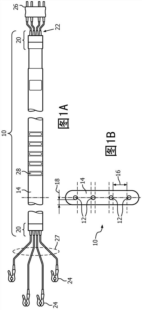
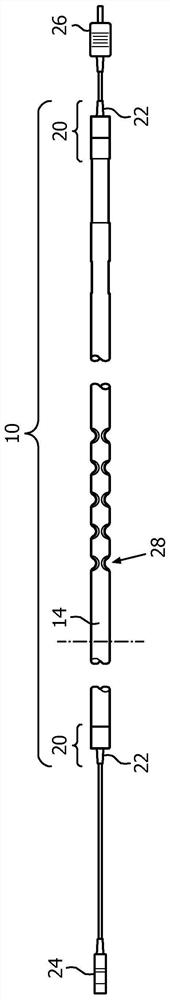
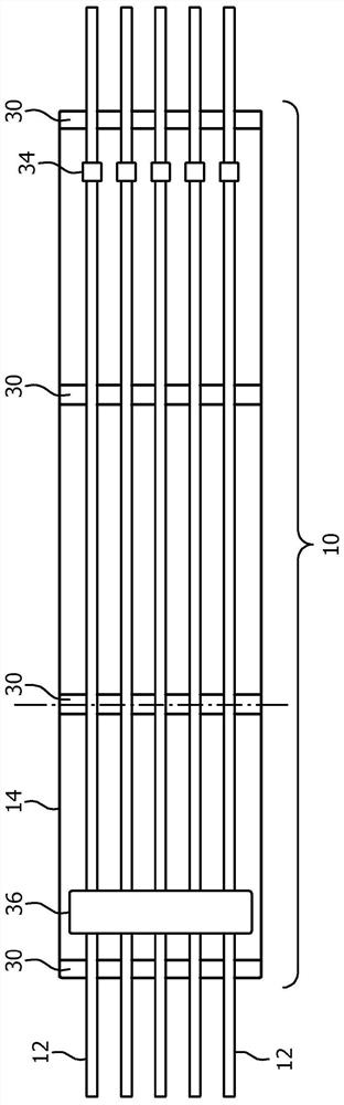
[0029] refer to Figure 1A , schematically illustrates an embodiment of a planar magnetic resonance (MR) safety cable 10 for biopotential measurements in top view. exist Figure 1B , the MR safety cable 10 is shown in cross-sectional view, and in Figure 1C , the MR security cable 10 is shown in side view. The cable 10 is shown with four controlled resistance conductive wires 12 arranged in a common plane and parallel to each other. In other embodiments, the cable can be configured to maintain any number of wires (eg, 4 to 12) in a common plane and parallel to each other. The wires transmit physiological signals, such as ECG signals in a strong magnetic field. The strong magnetic field can be that of a Magnetic Resonance Imaging (MRI) scanner. In one embodiment, the controlled resistance conductive lines include a distance 16 of at least 4mm between adjacent lines, although other distances are contemplated.

[0030] The cable 10 includes a rigid planar substrate 14 that ...


PUM


Abstract

A magnetic resonance (MR) safety cable (10) comprising: four or more controlled resistance conductive wires (12) arranged in a parallel plane configuration; and a hard non-proton emitting substrate (14), It maintains the four or more controlled resistance conductive lines in the parallel plane configuration. The wire (12) terminates at one end in a connector electrically connected to ECG electrodes (64) attached to the subject. The cable is configured to extend one end into the imaging region of the MR scanner (62) to carry ECG signals to associated equipment during imaging.

Description

technical field [0001] The following generally relates to magnetic resonance (MR) imaging. It finds particular application in connection with electrocardiography (ECG) during MR imaging and will be described with particular reference thereto. However, it should be understood that it is also applicable to other use cases and is not necessarily limited to the aforementioned applications. Background technique [0002] MR imaging often involves biopotential measurements, such as ECG monitoring during imaging procedures. The ability to monitor the patient for vital signs with an ECG or other monitor during the MR procedure to ensure patient health. An ECG monitor can be used in MR imaging as a trigger or gate for image acquisition. For example, the images can be triggered such that the subject's heart only shows cardiac motion artifacts in the image in a particular phase or in its compensated image. [0003] ECG monitoring uses electrodes attached to the patient at various po...

Claims


Application Information

Patent Timeline
Patent Type & Authority Patents(China)
IPC IPC(8): A61B5/271A61B5/28A61B5/321A61B5/33A61B5/055A61B5/308
CPCA61B5/055A61B2017/00911A61B2562/12A61B5/303A61N1/08A61N1/37A61B5/30A61B5/316A61B2562/125G01R33/4808
Inventor F·P·奥尼尔E·M·雷伊D·A·福雷尔
Owner KONINKLJIJKE PHILIPS NV
Why Eureka
Try Eureka