System for automatically testing display and television power modules

An automatic test system and power module technology, applied in the direction of power supply testing, etc., can solve problems such as low operating efficiency, long testing time, and hazards to operators, and achieve the effects of reducing testing time, improving operating efficiency, and avoiding potential safety hazards

Inactive Publication Date: 2011-05-04
TPV ELECTRONICS (FUJIAN) CO LTD
View PDF4 Cites 0 Cited by
  • Summary
  • Abstract
  • Description
  • Claims
  • Application Information

AI Technical Summary

Problems solved by technology

The test process is as figure 2 As shown, the operator needs to look at 7 measurement data during the whole test process, the test time is long, a single module takes about 25 seconds, and the efficiency is low
And there are the following deficiencies: 1. The measurement results are determined by humans, and there are production test leakage factors; 2. During the test process of the power module, many external connections need to be plugged and unplugged, and the work efficiency is low; 3. The power module needs to be functionally tested. It must be powered on, and all its circuits and components are exposed during the test. If the module is defective, the possible component explosion will cause harm to the workers; 4. The power module contains high-voltage parts (mains input and High voltage generated by itself), because the line is exposed outside, if you touch this part during operation, you will be shocked by electric shock, posing a safety hazard

Method used


Image

  • System for automatically testing display and television power modules
  • System for automatically testing display and television power modules
  • System for automatically testing display and television power modules

Examples


Embodiment Construction

[0018] The present invention will be further described below in conjunction with the accompanying drawings and implementation examples.

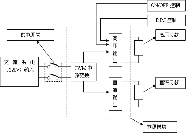
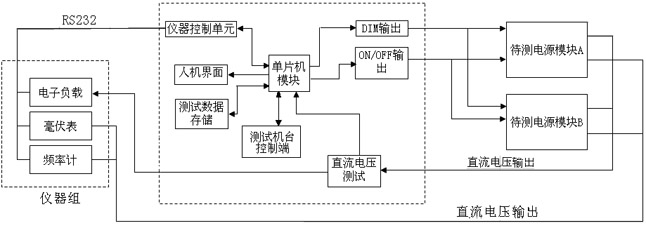
[0019] Such as image 3 As shown, the present invention provides an automatic test system for display and TV power supply modules, including a test machine and a tested power module, characterized in that: the test machine includes power supply probes for the tested power module, DIM control output Probe, ON / OFF control output probe, the first probe for detecting the DC output end of the power module under test and the second probe for detecting the AC output end of the power module under test; the input end of the power supply probe of the power module under test Connect 220V AC; the input ends of the DIM control output probe and the ON / OFF control output probe are respectively connected with a single-chip microcomputer; the output control terminal of the single-chip microcomputer is connected with the control terminal of the test machine; ...


PUM


Abstract

The invention relates to a system for automatically testing display and television power modules. The system comprises a testing bench and a tested power module, and is characterized in that: the testing bench comprises a probe for supplying power to the tested power module, a DIM control output probe, an ON/OFF control output probe, a first probe for detecting a direct current output end of the tested power module, and a second probe for detecting an alternating current output end of the tested power module, wherein an input end of the probe for supplying power to the tested power module is connected with 220V alternating current; input ends of the DIM control output probe and the ON/OFF control output probe are connected with a singlechip respectively; and an output control end of the singlechip is connected with a control end of the testing bench. The system can automatically test the power modules, the working efficiency is improved, the action of plugging/unplugging wires is removed, and the testing time, the number of testing instrument and manual labor are reduced.

Description

technical field [0001] The invention relates to an automatic test system for display and TV power supply modules, which is mainly used in the functional test field of the production lines of display and TV power supply modules. Background technique [0002] The working status of the existing display and TV power supply is as follows: figure 1 As shown in the figure, the main components of the power module are inside the dotted box in the figure. When the power supply switch is closed, AC220V power is input to the power module, and after PWM power conversion, it is converted into two parts of "high voltage output" and "DC output", which supply power to "high voltage load" and "DC load" respectively. "High-voltage load" refers to the PANNEL lamp, which needs a specified AC high voltage to be lit. "DC load" refers to the components in the monitor or TV that require DC power to work, such as the Main Board, etc. "High voltage load" also needs two control signals: "ON / OFF con...

Claims


Application Information

Patent Timeline
Patent Type & Authority Applications(China)
IPC IPC(8): G01R31/40
Inventor 张新华吴俊彭烜
Owner TPV ELECTRONICS (FUJIAN) CO LTD
Why Eureka
Try Eureka