Reaping part of a combine

A technology for combine harvesters and harvesting parts, which is applied to the chassis and cutters of harvesters and agricultural implements, can solve the problems of complex structure of cutting devices, and achieve stable cutting performance, simplified structure, and reduced vibration and noise. Effect

Inactive Publication Date: 2011-05-04
YANMAR CO LTD
View PDF1 Cites 2 Cited by
  • Summary
  • Abstract
  • Description
  • Claims
  • Application Information

AI Technical Summary

Problems solved by technology

[0005] Although the reaping section of the conventional combine harvester can seek to reduce the vibration and noise generated by the cutting device, it is necessary to set a plurality of disc-shaped cutting knives with respect to a raised ridge bar. Depending on the model of the combine harvester, when the cutting width of the cutting device of the harvesting section is different, it is necessary to use cutting knives with different diameters
Therefore, in the harvesting section of the combine harvester, the structure of the cutting device becomes complicated

Method used


Image

  • Reaping part of a combine
  • Reaping part of a combine
  • Reaping part of a combine

Examples


Embodiment Construction

[0036] Next, embodiments of the present invention will be described.

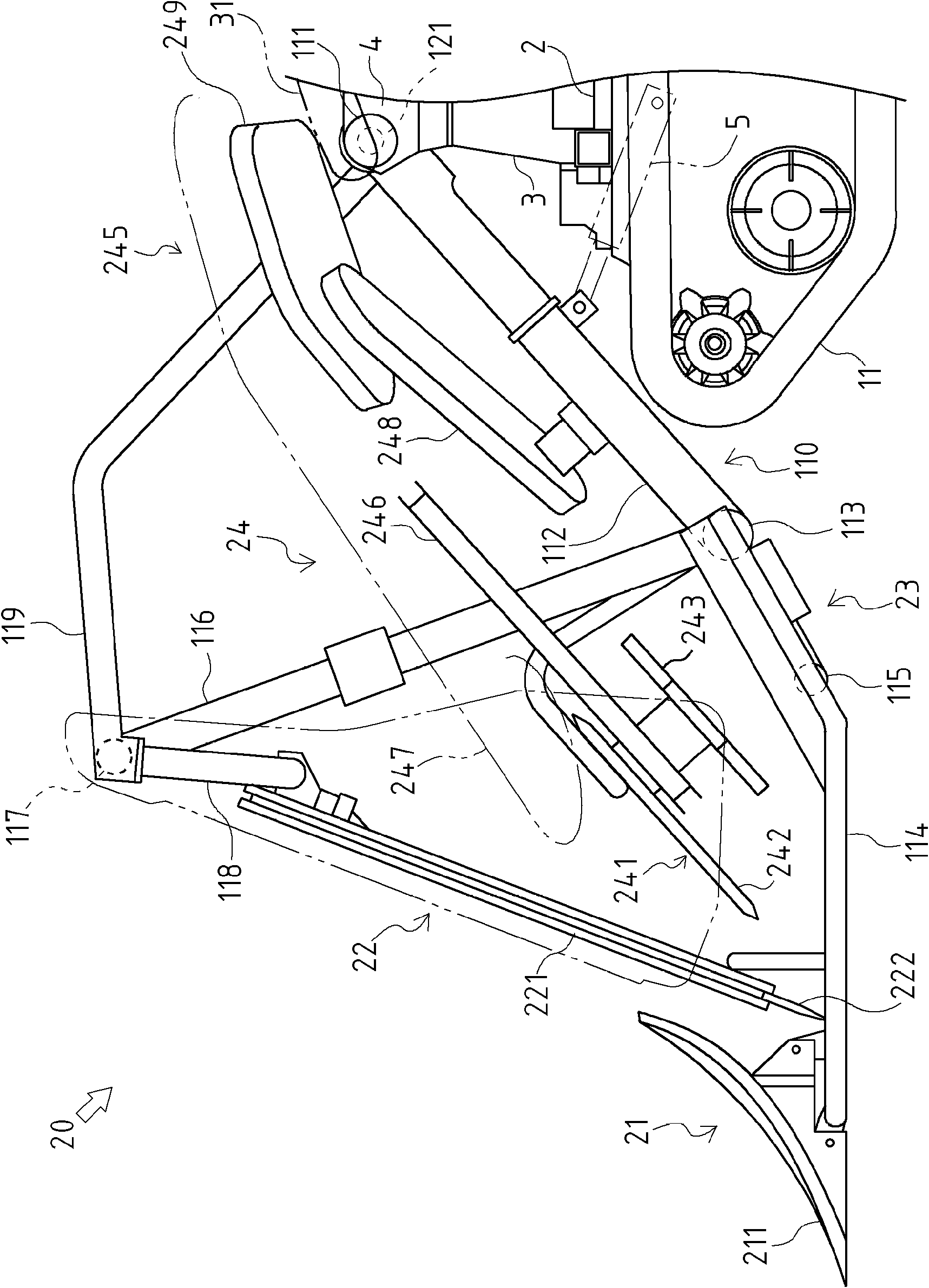
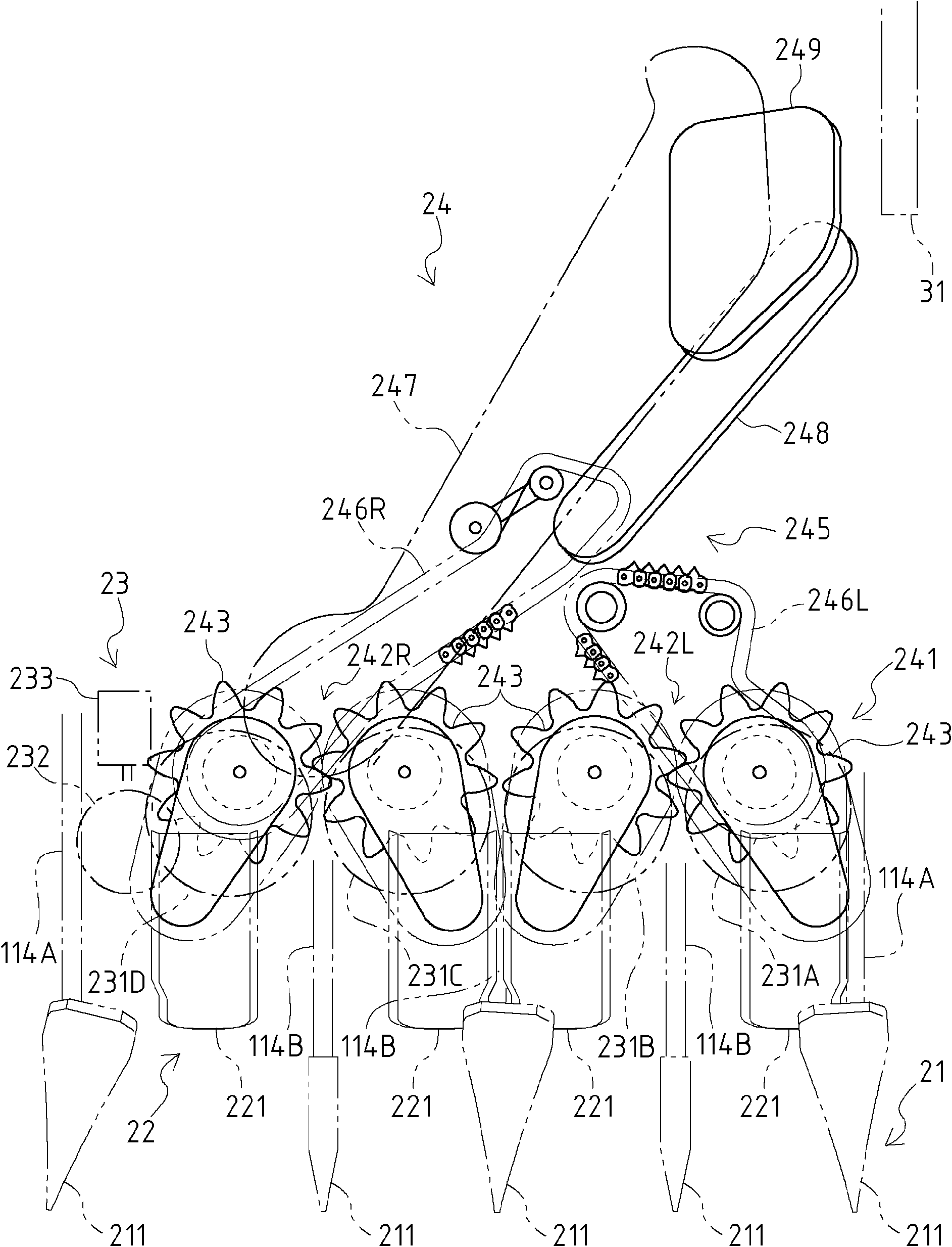
[0037] First, the whole structure of the combine 1 for four-row harvesting which has the harvesting part 20 concerning one Embodiment of this invention is demonstrated. In addition, the harvesting part concerning this invention is not limited to the combine harvester of four-row harvesting, The combine harvester of multi-row harvesting can also be applied.

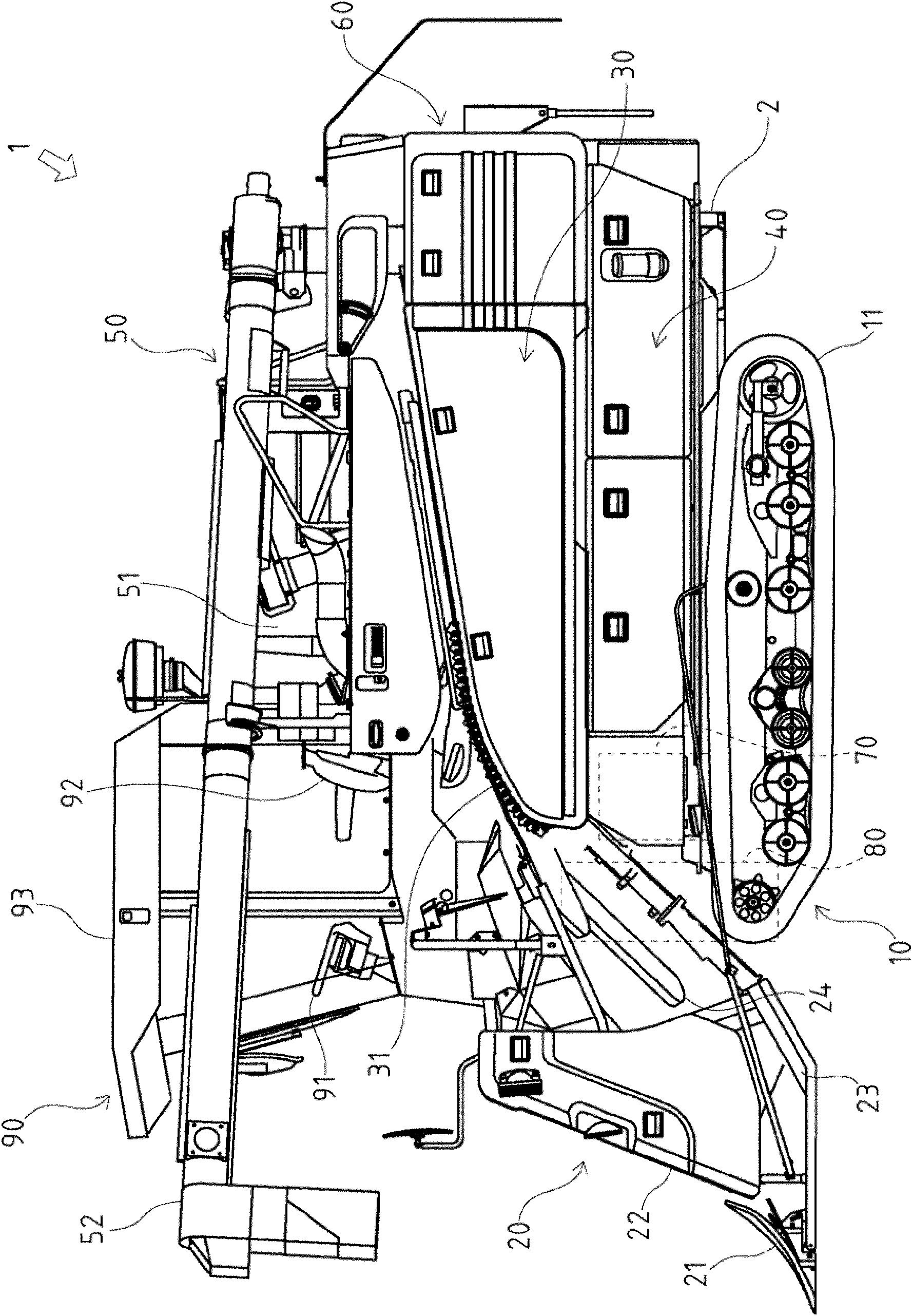
[0038] like figure 1 As shown, the combine harvester 1 is equipped with a walking part 10, a harvesting part 20, a threshing part 30, a sorting part 40, a grain storage part 50, a rice straw processing part 60, an engine part 70, and a transmission part with respect to the body frame 2. 80 and the control unit 90.

[0039] The running part 10 is arranged on the lower part of the body frame 2 . The traveling unit 10 is configured to include a crawler-type traveling device 11 and the like, and the crawler-type traveling device 11 has a pair of left and...


PUM


Abstract

Provided is a reaping part of a combine in which vibration and noise generated by the cutting device is reduced and the configuration of the cutting device is simplified. In the reaping part of the combine, the cutting device (23) is provided with multiple disc-shaped cutting blades (231) that cut stalks at the base and one disc-shaped auxiliary cutting blade (232) that is configured with a smaller diameter than cutting blades (231) and that cuts the stalks at the base, all blades being rotatable. The multiple cutting blades (231) are arranged on roughly the same line in the left-to-right direction. The auxiliary cutting blade (232) is positioned to the outside of either the right or left outermost cutting blade (231) of the multiple cutting blades (231).

Description

technical field [0001] The present invention relates to a harvesting section of a combine harvester for harvesting grain stems. Background technique [0002] Conventionally, the harvesting part of the combine equipped with the cutting device which cuts the raised grain stem is well-known. In the harvesting section of such a combine harvester, the cutting device is configured to include a fixed blade and a movable blade extending in the left-right direction as a cutting blade for cutting the grain stalks, and the fixed blade and the movable blade are stacked up and down. In the state, by making the movable knife reciprocally slide relative to the fixed knife, the movable knife cuts the grain stalk. [0003] However, in such a cutting device, there is a problem that large vibration and noise are generated at the time of grain stem cutting by the fixed blade and the movable blade. Then, in order to solve this problem, it is proposed to use the disc-shaped cutting blade as a c...

Claims


Application Information

Patent Timeline
Patent Type & Authority Applications(China)
IPC IPC(8): A01D34/63A01D67/00
CPCA01D41/14
Inventor 森山浩二野村浩久今田光一
Owner YANMAR CO LTD
Why Eureka
Try Eureka