
Method and filling system for filling bags

A technology of filling equipment and pockets, which is applied in the field of valve pockets, can solve problems such as increased operating costs, achieve the effects of optimizing output, avoiding material leakage, and improving efficiency

Active Publication Date: 2011-05-04
HAVER & BOECKER
View PDF1 Cites 14 Cited by
  • Summary
  • Abstract
  • Description
  • Claims
  • Application Information

AI Technical Summary

Problems solved by technology

All in all, this situation means an increase in operating costs

Method used


Image

  • Method and filling system for filling bags
  • Method and filling system for filling bags
  • Method and filling system for filling bags

Examples


Embodiment Construction

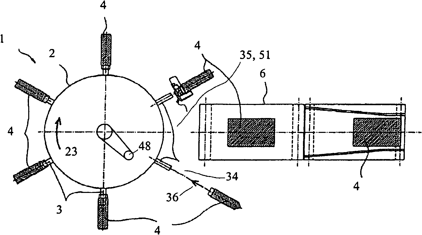
[0074] figure 1 The illustrated filling plant 1 according to the invention comprises a rotary packaging machine 2 which can be driven in the direction of the arrow 23 by means of a drive 48 . The speed of the drive 48 in the form of an electric motor is controlled accordingly in order to control or regulate the rotational speed of the packaging machine 2 .

[0075] The packaging machine 2 includes 6 filling mechanisms in the form of filling nozzles 3, such as Figure 4 In particular, a valve bag 4 with an opening 5 in the form of a valve port is pushed onto the filling spout 3 .

[0076] as in figure 1 According to the invention, the valve bag 4 comes from stock and is removed by means of a gripping mechanism not shown in the drawing and inserted and hung on the filling nozzle 3 by an automatic bag inserting machine, as indicated by arrow 36 in the figure.

[0077] The filling equipment 1 is equipped with a bag unloading conveyor belt 6 for sending away the filled and dumped ...


PUM


Abstract

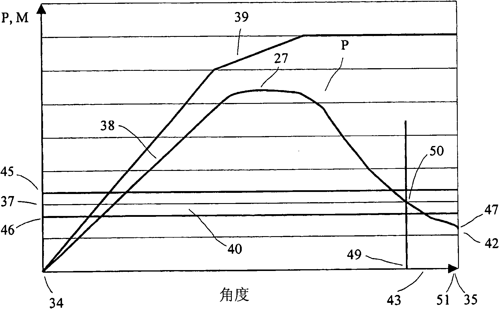
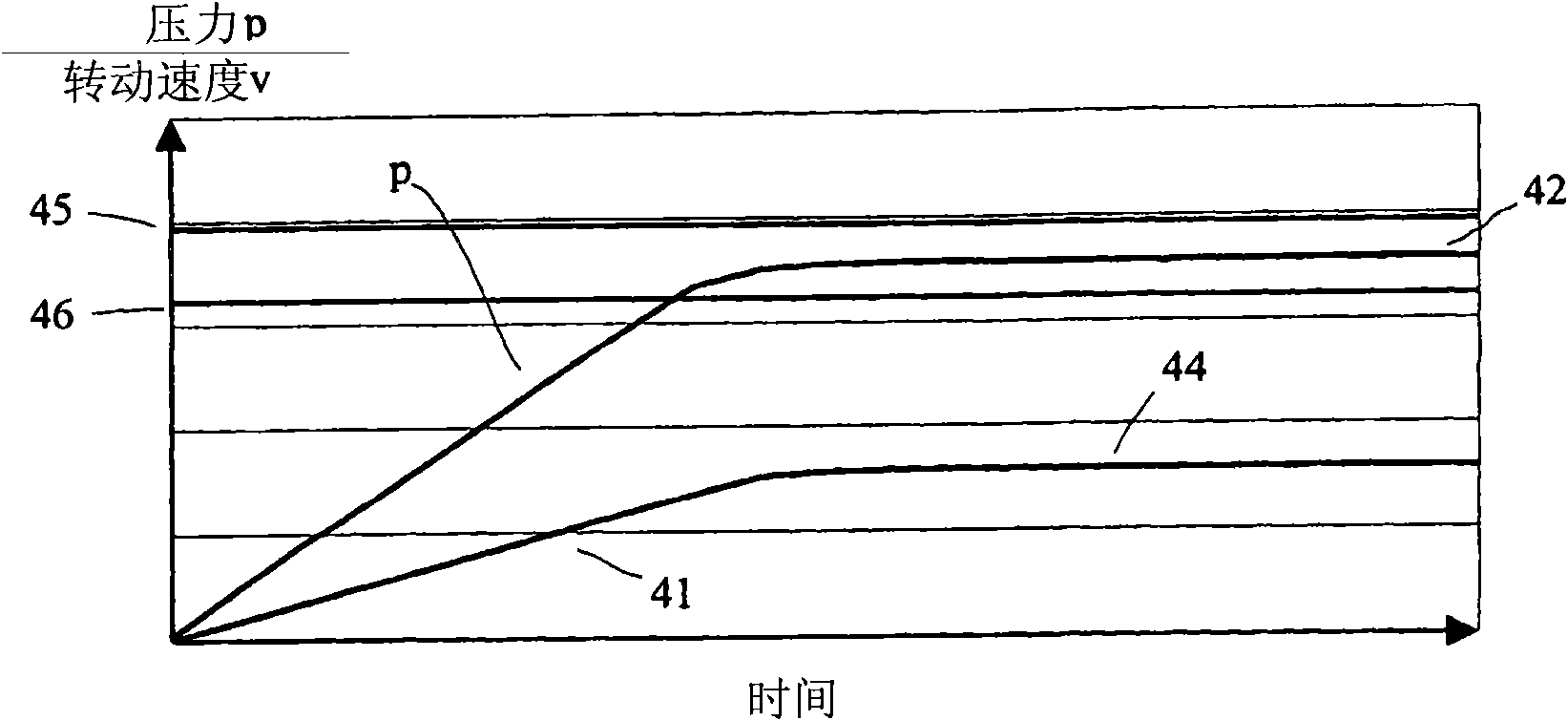
The invention relates to a filling system for filling valve bags, and to a method for operating a filling system, which comprises at least one rotating packing machine having a drive for rotating the packing machine, and a plurality of filling nozzles, which are distributed across the periphery of the rotating packing machine. The filling nozzles are provided for receiving the valve bags and can be fixed to the filling nozzles at an opening, and they may be filled with a pourable material through the filling nozzles. The valve bags are placed onto the filling nozzles at a defined insertion position and are automatically released at a defined release position. The invention provides a controller in order to control the filling process. A pressure sensor (10) is associated with at least one filling nozzle in order to determine a degree of the filling pressure of the valve bag disposed at the filling nozzle. The controller determines a representative characteristic pressure value for the filling pressure present at a predetermined position (51) in front of the release position by means of a pressure sensor, and adjusts a rotational speed of the packing machine to the speed of the drive by way of a control unit.

Description

technical field [0001] The invention relates to a filling plant comprising a rotary packaging machine and a method of filling containers, especially bags, preferably valve bags, with bulk material. The filling device comprises at least one filling nozzle, by means of which a container is supplied with bulk material and at which the container is placed. Furthermore, a conveying mechanism is provided for conveying the material into the container via the filling mechanism. Background technique [0002] Bulk materials such as building materials or chemicals, especially in granular or powder form, are usually filled into valve bags with rotary packaging machines. The sealed valve bag is then sent to the user. [0003] Various bulk material filling systems are disclosed in the prior art. In conventional filling systems where bulk material is filled into valve pockets, the bulk material contains a certain amount of air. Also, air is often added to the material during bagging to...

Claims


Application Information

Patent Timeline
Patent Type & Authority Applications(China)
IPC IPC(8): B65B1/18
CPCB65B1/18B65B43/60
Inventor A·科姆布林克T·希灵
Owner HAVER & BOECKER
Learn More