
Heat exchanger

A technology for heat exchangers and heat conduction parts, applied to heat exchange equipment, indirect heat exchangers, heat exchanger types, etc., can solve the problem of reduced drainage and achieve high contact reliability

Active Publication Date: 2011-05-04
DAIKIN IND LTD
View PDF2 Cites 13 Cited by
  • Summary
  • Abstract
  • Description
  • Claims
  • Application Information

AI Technical Summary

Problems solved by technology

[0003] However, in the situation where the miniaturization of heat exchangers is further progressing, there is a high possibility that the miniaturization of heat exchangers will reduce the drainage performance of the heat exchanger to dew condensation water, so further improvement of drainage performance is sought.

Method used


Image

  • Heat exchanger
  • Heat exchanger
  • Heat exchanger

Examples


Embodiment Construction

[0027] Hereinafter, embodiments of the present invention will be described with reference to the drawings. In addition, the following embodiments are only specific examples of the present invention, and do not limit the technical scope of the present invention.

[0028]

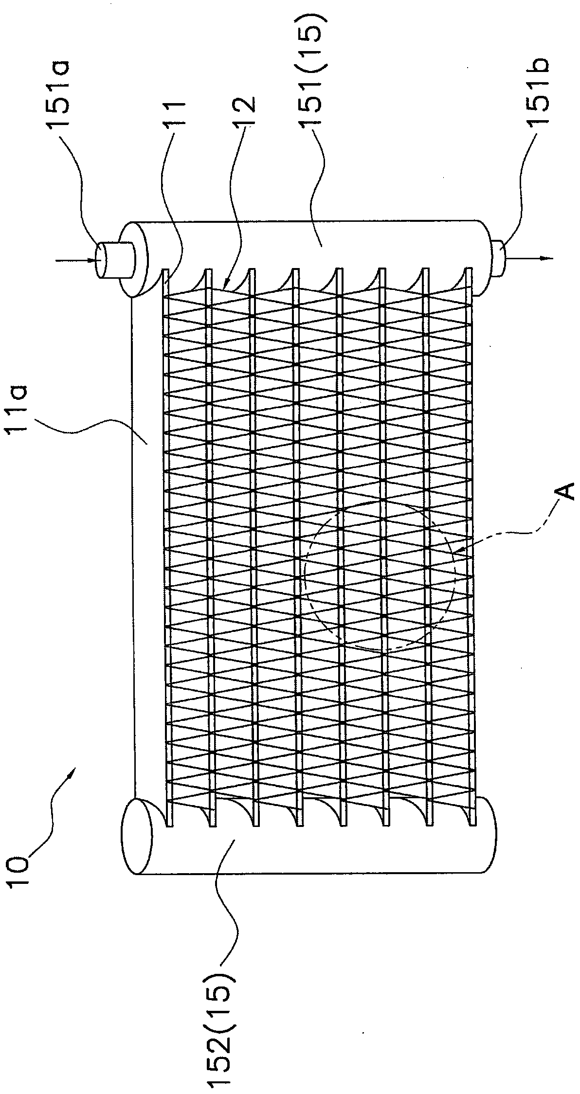
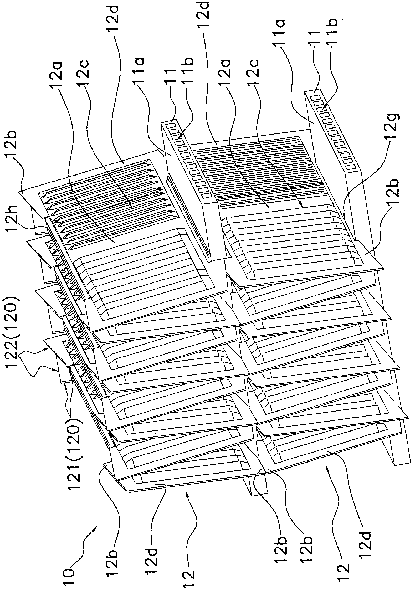
[0029] figure 1 is an external perspective view of a heat exchanger according to an embodiment of the present invention, figure 2 yes figure 1 An enlarged perspective view of part A of . exist figure 1 , figure 2 Among them, the heat exchanger 10 includes flat tubes 11 , corrugated fins 12 , and headers 15 .

[0030] (flat tube 11)

[0031] The flat tube 11 is formed of aluminum or an aluminum alloy, and has a flat portion 11a serving as a heat transfer surface and a plurality of refrigerant passages 11b through which the refrigerant flows (refer to figure 2 ). Such as figure 2 As shown, the flat tubes 11 are arranged in a plurality of stages with the planar portions 11a facing the up-down dire...


PUM


Abstract

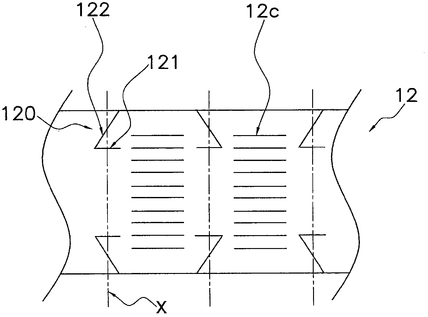
A heat exchanger from which condensation water is more smoothly discharged. In a heat exchanger (10), first cut lines (121) and second cut lines (122) are formed in a blank material for corrugated fins (12) before the blank material is bent in corrugations. The first cut lines (121) each cross an imaginary center line (X) of a bent section of the corrugations, and the second cut lines (122) each extend from the vicinity of an end of the first cut line (121) and cross the imaginary center line (X). When the blank plate is bent, acute-angled triangle portions sandwiched between the first cut lines (121) and the second cut lines (122) are raised to form cut-and-raised sections (12b). The distance between the top and root of each cut-and-raised section (12b) is greater than that of conventional products to increase the amount of contact between cut-and-raised sections (12b) adjacent to each other in the top-bottom direction. This allows condensation water to more easily flow through the cut-and-raised sections (12b), improving water discharge ability of the heat exchanger.

Description

technical field [0001] The present invention relates to a heat exchanger including flat tubes and fins. Background technique [0002] Conventionally, heat exchangers in which planar portions of flat tubes are arranged horizontally and fins are arranged between the planar portions have been widely used (see Patent Document 1). The heat exchanger disclosed in Patent Document 1 has a protruding portion protruding from the fin toward the downstream side of the air flow, and a notch is provided in the protruding portion. The dew condensation water generated in the heat exchanger collects on the downstream side of the air flow, and falls downward from the notch. However, the dew water will fall from the gap when the dew water grows to a size that can fall by its own weight. Otherwise, the dew water will temporarily stay in the heat exchanger, and the dew water will become ventilation resistance and reduce the heat exchange performance. Therefore, the applicant has developed a he...

Claims


Application Information

Patent Timeline
Patent Type & Authority Applications(China)
IPC IPC(8): F28F1/30F28F1/32
CPCF28D1/05391F28F1/128F28F1/325F28F1/34F28F17/005F28D1/04F28F1/30F28F1/32
Inventor 金铉永中田春男藤野宏和镰田俊光
Owner DAIKIN IND LTD
Learn More