
Forming method and forming die device for sealing ring used in engine

A technology for forming a mold and a sealing ring, which is applied to the field of sealing ring forming and mold device in an engine, can solve the problems of difficult forming and large forming difficulty, and achieves improved surface quality and dimensional accuracy, less matching quantity, and good versatility. Effect

Inactive Publication Date: 2011-05-11
BEIHANG UNIV
View PDF7 Cites 10 Cited by
  • Summary
  • Abstract
  • Description
  • Claims
  • Application Information

AI Technical Summary

Problems solved by technology

Therefore, the forming of this part is quite difficult, and it is difficult to form it by traditional processing methods.

Method used


Image

  • Forming method and forming die device for sealing ring used in engine
  • Forming method and forming die device for sealing ring used in engine
  • Forming method and forming die device for sealing ring used in engine

Examples


Embodiment Construction

[0080] The technical solution of the present invention will be further described below in conjunction with the accompanying drawings.

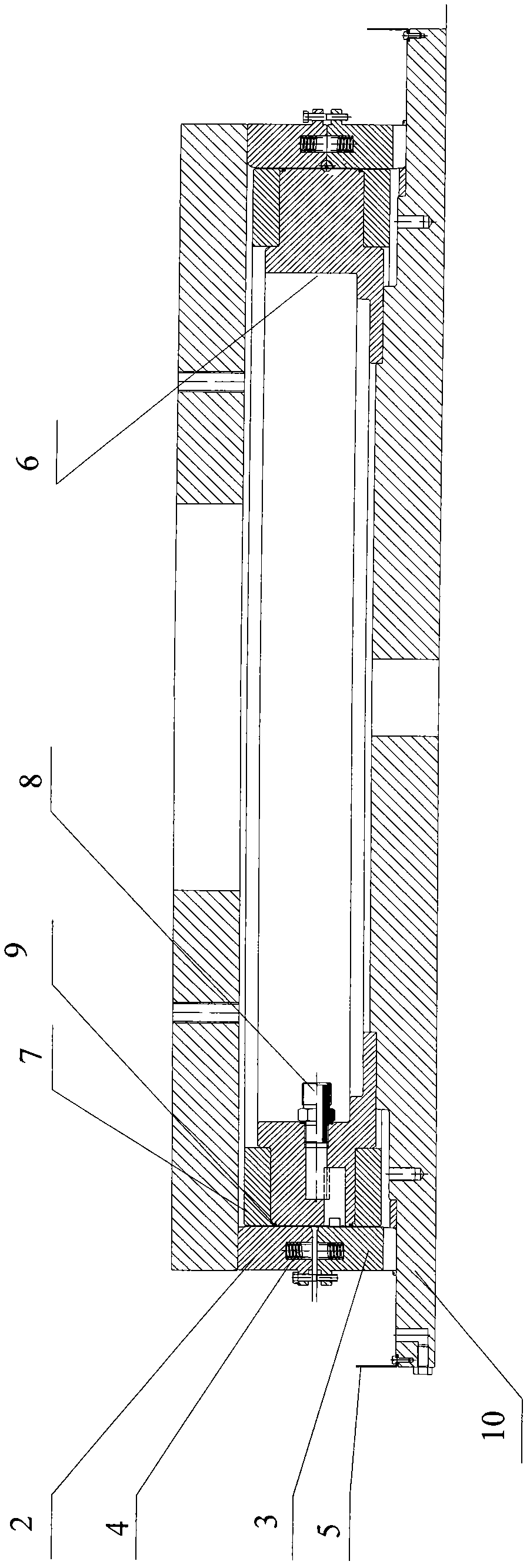
[0081] A sealing ring forming die device used in an engine, comprising an initial forming die and a final forming die,

[0082] Among them, the initial forming die, such as figure 1 shown, including:

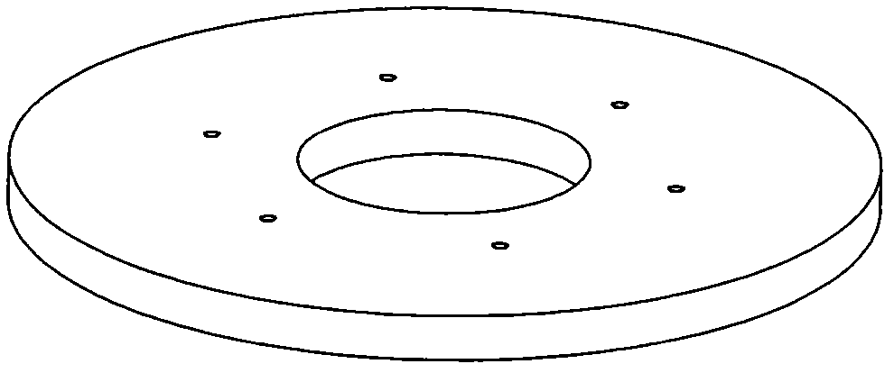
[0083] A platen 1 (such as figure 2 , 3 ), which is a disc with a circular hole in it, fixed with the first upper die by six bolts.

[0084] - the first upper mold 2 (such as Figure 4 , 5 , 6), be a ring, have four spring slots for installing springs on the lower end face of the ring, and have a circle of flash near the lower end face, and have 4 holes with a diameter of 16mm on the flash.

[0085] - the first die 3 (such as Figure 7 , 8 , 9), the shape is similar to that of the first upper mold, which is a ring, and there are four spring grooves for installing springs on the upper end surface of the ring, and there is a circle of fla...


PUM


Abstract

The invention relates to a forming die device for a sealing ring used in an engine. The device comprises a primary forming die and a final forming die, wherein the primary forming die specifically comprises a pressure plate, a first upper die, a first lower die, a supporting spring, an oil baffle pan, a base, an internal mold column, a sealing end cover, an oil guide pipe adapter, and the like; and the final forming die specifically comprises a pressure plate, a second upper die, an upper locking lantern ring, a lower locking lantern ring, a second lower die, an oil baffle pan, an intermediate model, a base, an internal mold column, a sealing end cover, and the like. The forming method for the sealing ring used in the engine comprises the following two steps of primary forming and final forming.

Description

technical field [0001] The invention relates to a molding method and a mold device for a sealing ring used in an engine, in particular to a molding method and a mold device for an omega ring used in an aero-engine, and is suitable for a production process of a complex section ring sealing ring. Background technique [0002] Complex tiny Ω-rings are mainly used in the sealing of aero-engines. This part has remarkable characteristics such as high material strength, complex cross-sectional shape, small feature size and large relative size, which is difficult to realize by traditional processing methods. At present, there is no domestic production capacity, and it mainly relies on imports from abroad. The price of each piece is tens of thousands of dollars, which is quite expensive. Therefore, it is imperative to study a set of manufacturing processes suitable for such parts. [0003] The basic dimensions of the parts are as figure 1 Shown: One of the typical parts is figure ...

Claims


Application Information

Patent Timeline
IPC IPC(8): B21D26/031B21D26/021
Inventor 郎利辉王永铭周贤宾段新民邵天巍陈汇
Owner BEIHANG UNIV
Learn More