Core jig

A core clamping and sand core technology, which is applied in manufacturing tools, casting and forming equipment, metal processing equipment, etc., can solve the problems of low work efficiency, easy deviation in accuracy, and sand core crushing, etc., and achieves the effect of simple operation and simple structure.

Active Publication Date: 2011-05-11
SUZHOU MINGZHI TECH
View PDF10 Cites 1 Cited by
  • Summary
  • Abstract
  • Description
  • Claims
  • Application Information

AI Technical Summary

Problems solved by technology

However, the core-setting fixture of this type of structure generally has the following defects: during the core-setting process, when the clamping part is pulled out from the sand core, the sand core will float up to a certain extent due to the upward pulling force of the clamping part. It is necessary to press t

Method used


Image

  • Core jig
  • Core jig
  • Core jig

Examples


Embodiment Construction

[0016] The present invention will be further described below in conjunction with accompanying drawing and embodiment:

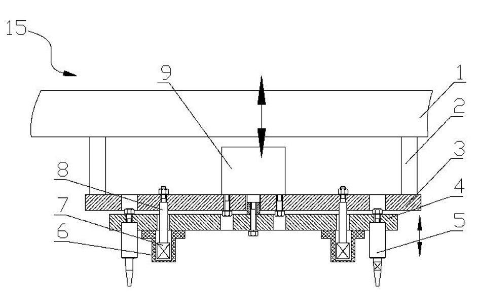
[0017] Such as figure 1 A lower core clamp 15 is shown, which is used to take out the sand core from the lower core mold 14 and send it into the mold cavity 13 on the pouring line.

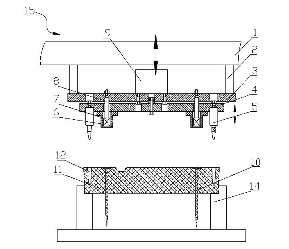
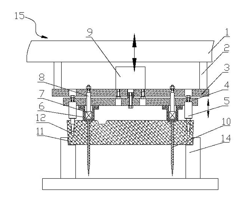
[0018] Wherein: the sand core includes a sand core body 11, a positioning hole 12 is opened on the top of the sand core body 11, and a plurality of iron nails 10 are interspersed on the sand core body 11, and the flat ends of the iron nails 10 are located on the upper part of the sand core body 11 , the sharp end of the iron nail 10 passes through the lower part of the sand core body 11 .

[0019] The lower core fixture 15 includes a frame 1, a fixed plate 3 connected to the frame 1 through a connector 2, a push plate 4 that is located below the fixed plate 3 and can slide up and down relative to the fixed plate 3, and drives the push plate 4 up and down relative to the fixed pl...


PUM


Abstract

The invention relates to a core jig which is used for taking out a sand core from a core setting mould and feeding the sand core into a cavity on a pouring line, wherein the sand core comprises a sand core body; a positioning hole is formed at the top of the sand core body; multiple iron nails are inserted into the sand core body; the flat end of each iron nail is positioned at the upper part of the sand core body, and the sharp end of each iron nail penetrates through the lower part of the sand core body; the core jig comprises a frame, a fixing plate, a pushing plate, a driving mechanism and a locating pin; the fixing plate is connected to the frame; the pushing plate is positioned below the fixing plate and can slide up and down relative to the fixing plate; the driving mechanism drives the pushing plate to slide up and down relative to the fixing plate; the locating pin is arranged on the pushing plate and matched with the positioning hole; and the lower part of the pushing plate is provided with an electromagnetic attraction head which absorbs the sand core through the iron nails. The core jig provided by the invention can ensure that the sand core put in the cavity does not float upward without additionally using compaction stone for the sand core in the core setting process, is simple in structure and convenient to operate, and can be widely applied to the mechanical or automatic production line of batch production.

Description

technical field [0001] The invention relates to a core setting fixture. Background technique [0002] The core clamp is generally used to clamp the sand core and transfer the core accurately. At present, the core setting fixture in the prior art mainly includes a clamping part and a moving part for transferring the clamping part to core setting. When operating the core setting fixture, the clamping part first extends into the sand core mold to clamp the sand core, and then transfers the sand core to the cavity through the moving part. However, the core-setting fixture of this type of structure generally has the following defects: during the core-setting process, when the clamping part is pulled out from the sand core, the sand core will float up to a certain extent due to the upward pulling force of the clamping part. It is necessary to press the sand core in the cavity manually or with a compacting stone, which is complicated to operate and low in work efficiency; at the ...

Claims


Application Information

Patent Timeline
IPC IPC(8): B22C19/00
Inventor 陆高春杨林龙吴勤芳邱壑
Owner SUZHOU MINGZHI TECH
Why Eureka
Try Eureka