Tool cleaning device

A technology for cleaning devices and tools, which is applied in the direction of manufacturing tools, metal processing equipment, metal processing machinery parts, etc., and can solve problems such as reduced processing accuracy, inability to locate, and instability

Active Publication Date: 2011-05-11
BROTHER KOGYO KK
View PDF4 Cites 5 Cited by
  • Summary
  • Abstract
  • Description
  • Claims
  • Application Information

AI Technical Summary

Problems solved by technology

The tool is not properly positioned relative to the spindle due to chips
Therefore, there is a problem that the tool rotates in an eccentric state, and the machining accuracy decreases
A machine tool including a tool cleaning device has a problem that the time required for tool replacement including tool cleaning is long, and the machining tim...

Method used


Image

  • Tool cleaning device
  • Tool cleaning device
  • Tool cleaning device

Examples


Embodiment approach 1

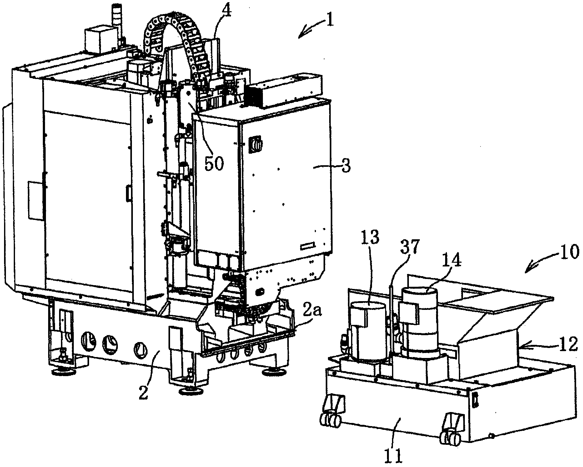
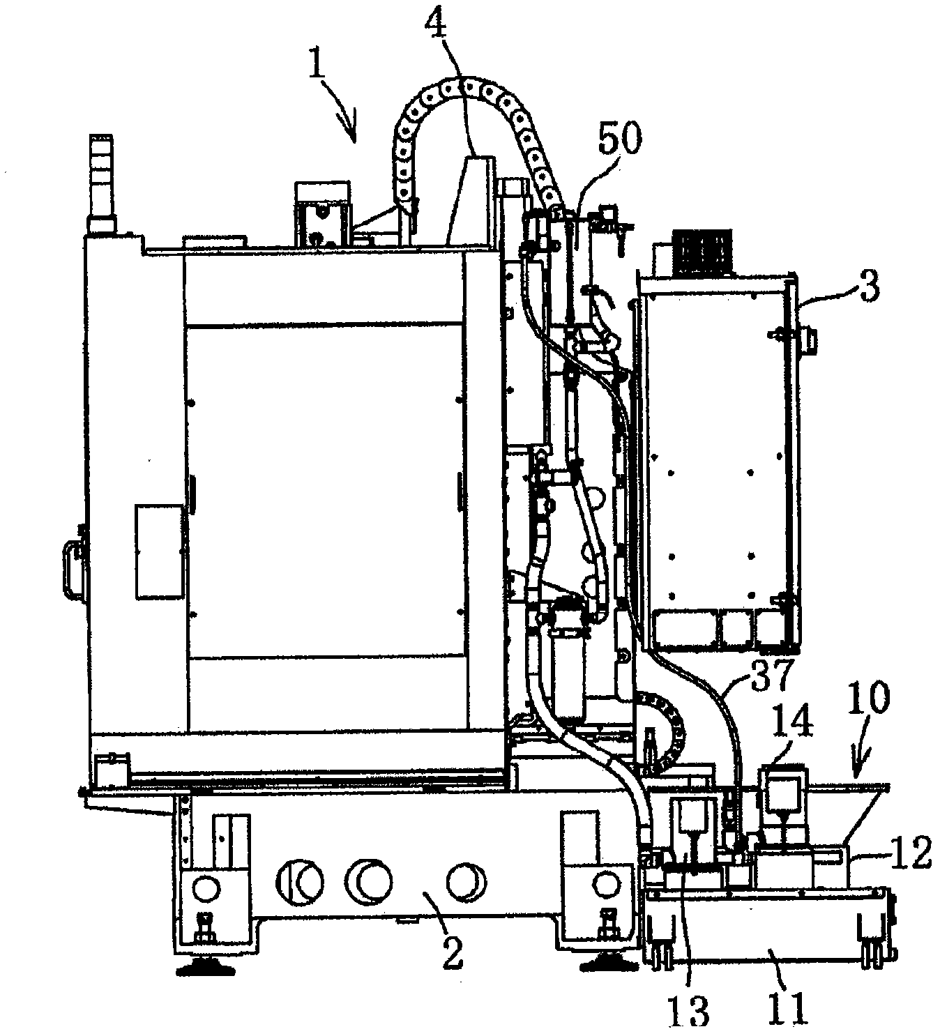
[0034] Such as Figure 1 ~ Figure 3 As shown, the machine tool 1 comprises a control box 3 and a column 4 on its base 2 supported on the floor. machine tool 1 figure 2 The left side of is the front (front). An operator operates machine tool 1 from the front (front). The column 4 is a support vertically erected at the center of the base 2 in the left-right direction and at the rear of the base 2 . Machine tool 1 includes being located at column 4 front side ( figure 1 , figure 2 on the left side) of the processing chamber. The processing chamber includes a processing table (not shown) movable in the front-rear direction and the left-right direction inside the processing chamber. The machine tool 1 processes the workpiece on the processing table inside the processing chamber.

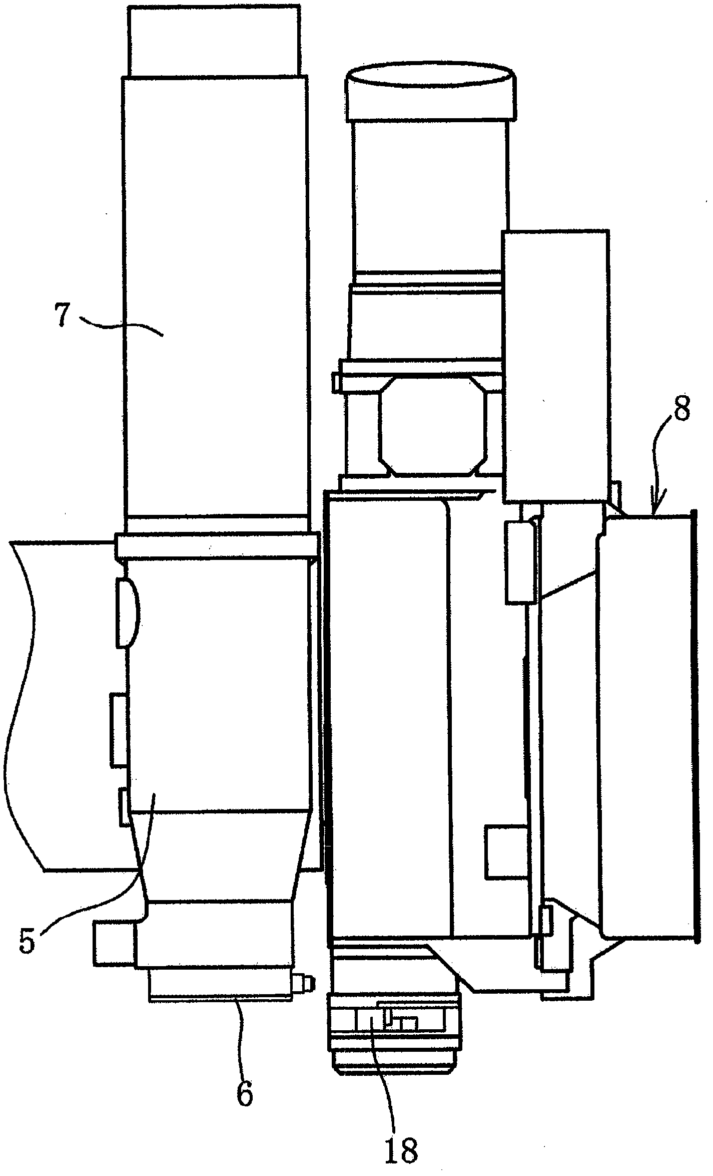
[0035] The column 4 supports a headstock 5 at its front (cf. image 3 ). The headstock 5 ascends and descends along the column 4 inside the machining chamber. The control box 3 is installed on...

Embodiment approach 2

[0087] Refer below Figure 10 , the tool cleaning device according to Embodiment 2 will be described. In the tool cleaning device according to Embodiment 2, the air passage 40 is branched into two air passages 60 and 62 on the downstream side of the first electromagnetic valve 43 . The air passage 60 is connected to the liquid supply valve 35 through a speed regulator 61 . The air passage 62 is connected to the pressurizing valve 45 . The speed regulator 61 includes a variable throttle valve 61a and a check valve 61b connected in parallel. The variable throttle valve 61 a provides resistance to the airflow in the air passage 60 . The one-way valve 61b allows the air flow to the liquid supply valve 35 in the air passage 60 to pass, and blocks the air flow to the first solenoid valve 43 .

[0088] During the cleaning operation, the control unit 9 opens the first electromagnetic valve 43 . The liquid supply valve 35 is opened by the air pressure applied through the air passa...

Embodiment approach 3

[0092] Refer below Figure 11 , the tool cleaning device according to Embodiment 3 will be described. In the tool cleaning device according to Embodiment 2, the air passage 40 is branched into two air passages 63 and 64 on the downstream side of the first electromagnetic valve 43 . The air passage 63 is connected to the pressurizing valve 45 . The air passage 64 is connected to the liquid supply valve 36 . Such as Figure 11 As shown, the length of the air passage 64 is much longer than the length of the air passage 63.

[0093] During the cleaning operation, the control unit 9 opens the first electromagnetic valve 43 . The pressurizing valve 45 is opened by the air pressure applied through the air passage 63 . The liquid supply valve 35 is opened by the air pressure applied through the air passage 64 . When the cleaning operation ends, the control unit 9 closes the first electromagnetic valve 43 . The first solenoid valve 43 discharges the air in the air passages 63 an...


PUM


Abstract

The invention provides a tool cleaning device which comprises an accumulating part at the middle of a cleaning fluid path. The accumulating part accumulates the cleaning fluid flowing in the cleaning fluid path. The tool cleaning device comprises a pressurization path for pressurizing the interior of the accumulating part. When a tool and a tool retainer are cleaned, the cleaning fluid in the accumulating part is sprayed out from a cleaning fluid jet nozzle. A great amount of cleaning fluid is sprayed out from the cleaning fluid jet nozzle with less resistance. When the cleaning is completed,the closing of a feed flow valve arranged at the cleaning fluid path is later than the closing of a pressurization valve arranged at the pressurization path. The cleaning fluid jet nozzle continues to inject after the releasing of pressurization. The tool and the tool retainer can be cleaned reliably by the cleaning fluid from the cleaning fluid jet nozzle. The tool cleaning device can effectively prevent the poor installation of the tool and the tool retainer.

Description

technical field [0001] The invention relates to a tool cleaning device for cleaning a tool and a tool holder mounted on a machine tool spindle. Background technique [0002] Machine tools perform a variety of machining by automatically changing tools. The machine tool includes a tool storage unit and a tool changer. The tool storage unit stores a plurality of tools while being held in the tool holder, and sends out necessary tools to the replacement position. The tool changer receives the tool at the change position, transports the received tool, and attaches it to the spindle of the machine tool. The tool changing device removes the used tool from the spindle, transports the removed tool to the changing position, and returns it to the tool storage section. [0003] The tool holder includes a spindle mounting portion and a tool holding portion. The spindle mounting portion has a conical shape. The tool holding part holds tools such as drill bits and taps. The spindle h...

Claims


Application Information

Patent Timeline
IPC IPC(8): B23Q11/00
Inventor 栗林裕
Owner BROTHER KOGYO KK
Why Eureka
Try Eureka