Electroplating device for composite plating electrodeposition

A technology of electroplating device and plating tank, which is applied in the direction of electrolytic coating, electrolytic process, electrolytic components, etc. It can solve the problems of no air inlet at the bottom of the plating tank, difficult control of the inclination angle of the cathode, unstable composite plating process parameters, etc. The effect of dispersion and stable process parameters

Inactive Publication Date: 2011-05-11
HARBIN INST OF TECH
View PDF3 Cites 0 Cited by
  • Summary
  • Abstract
  • Description
  • Claims
  • Application Information

AI Technical Summary

Problems solved by technology

[0003] The purpose of the present invention is to solve the problem that the anode cannot be tilted and fixed in the plating tank when using the inclined cathode method to electrodeposit the composite coating, and the inclination angle of the catho

Method used


Image

  • Electroplating device for composite plating electrodeposition
  • Electroplating device for composite plating electrodeposition
  • Electroplating device for composite plating electrodeposition

Examples


Example Embodiment

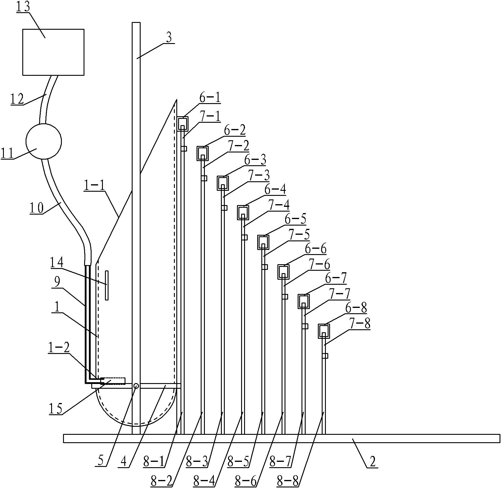
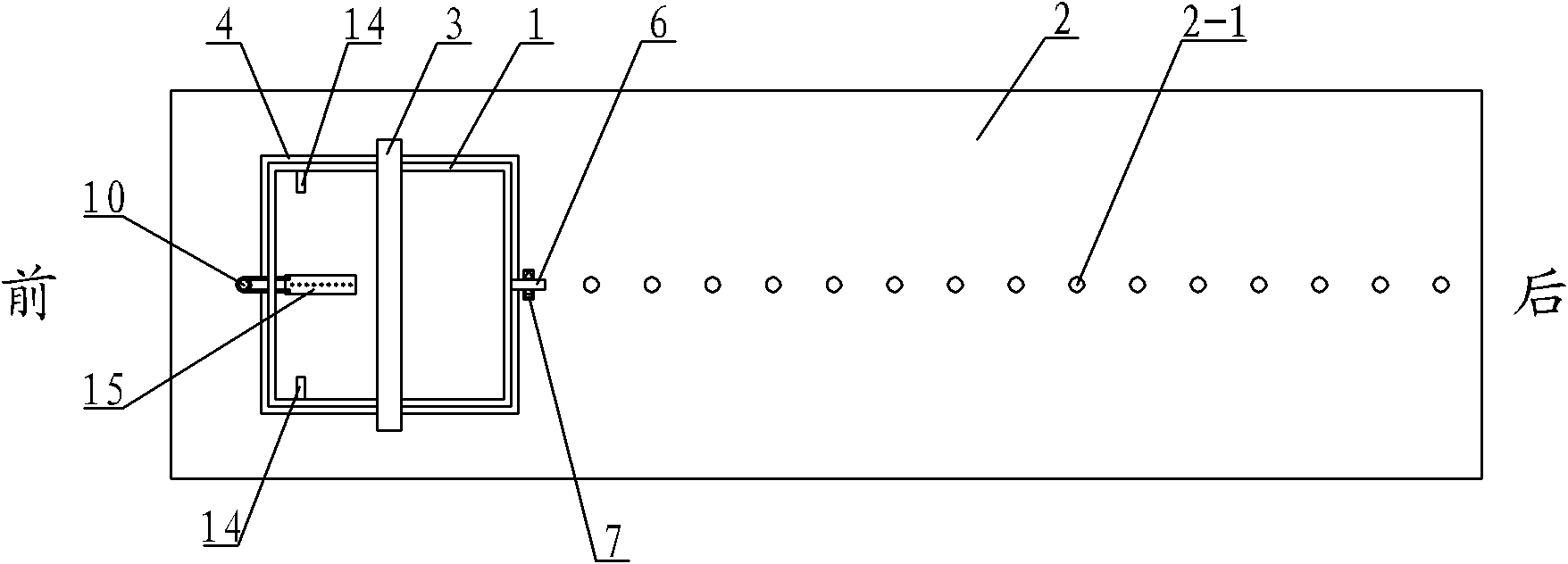
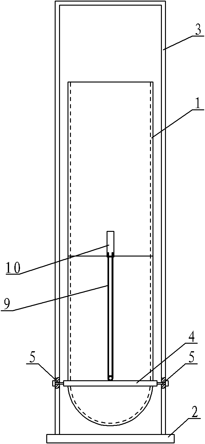
[0007] Specific implementation mode one: combine Figure 1 to Figure 5 Describe this embodiment, this embodiment includes a plating tank 1, a base 2, a frame support 3, a plating tank fixing ring 4, two rotating shafts 5, a first adjusting square ring 6-1, a first hook 7-1, a first plating tank Tank adjustment lever 8-1, the second adjustment square circle 6-2, the second hook 7-2, the second plating tank adjustment lever 8-2, the third adjustment square circle 6-3, the third hook 7-3, the second Three plating tank adjustment rods 8-3, fourth adjustment square rings 6-4, fourth hooks 7-4, fourth plating tank adjustment rods 8-4, fifth adjustment square rings 6-5, fifth hooks 7-5 , The fifth plating tank adjustment rod 8-5, the sixth adjustment square ring 6-6, the sixth hook 7-6, the sixth plating tank adjustment rod 8-6, the seventh adjustment square ring 6-7, the seventh hook 7 -7, the seventh coating tank adjustment rod 8-7, the eighth adjustment square ring 6-8, the eight...

Example Embodiment

[0008] Specific implementation mode two: combination figure 1 and figure 2 Describe this embodiment, the difference between this embodiment and specific embodiment 1 or 2 is that it also adds an air outlet pipe 15, and the air outlet pipe 15 is provided with a plurality of air outlet holes, and the air outlet pipe 15 is connected with the output end of the ventilation pipe 9. This design makes the air outlet pipe 15 replaceable and can be taken out for cleaning at any time. Multiple air outlets make the plating solution of composite plating more evenly stirred. Other components and connections are the same as those in the first embodiment.

Example Embodiment

[0009] Specific implementation mode three: combination figure 1 and Figure 5 To describe this embodiment, the air outlet pipe 15 of this embodiment is straight or Y-shaped. This design is suitable for plating tanks 1 of different sizes. When the outlet pipe 15 is Y-shaped, the lower end of the Y-shape is connected with the vent pipe 9 . Other components and connections are the same as those in the first embodiment.

[0010]The working principle of this device: the anode plate 16 is inserted between the tank wall of the coating tank 1 and the fixed plate 14, and then hung on the inner wall of the coating tank 1 to fix it, and the cathode plate 17 is hung in the coating tank 1 and connected with the On the opposite inner wall of the anode plate 16, the anode plate 16 and the cathode plate 17 are respectively connected with the anode and the cathode of the power supply 18 by wires; add an appropriate amount of plating solution in the plating tank 1, open the air pump 13, adju...


PUM


Abstract

The invention discloses an electroplating device for composite plating electrodeposition, which relates to a composite electroplating device and aims to solve the problems that an anode cannot be obliquely fixed in a plating bath, and the inclination angle of a cathode is difficult to control, so that the process parameters of composite plating are unstable, and solve the problem that the bottom of the plating bath is not provided with an air inlet. The open face of a frame bracket is vertical to a plurality of adjusting holes on a pedestal; a plating bath fixing ring is fixedly sleeved on the outer side wall of the plating bath; the components of the plating bath and the plating bath fixing ring are arranged in the frame bracket; the high side of the inclined plane of the frame bracket is faced to the adjusting holes; the plating bath fixing ring is connected with the frame bracket by a rotating shaft; the output end of a breather pipe is arranged in the plating bath; a first plating bath adjusting rod, a second plating bath adjusting rod, a third plating bath adjusting rod, a fourth plating bath adjusting rod, a fifth plating bath adjusting rod, a sixth plating bath adjusting rod, a seventh plating bath adjusting rod and an eighth plating bath adjusting rod are sequentially arranged in the adjusting holes from the plating bath to the rear part of the pedestal; and the height of the adjusting rods is gradually reduced. The electroplating device for composite plating electrodeposition is used for metal surface processing.

Description

technical field [0001] The invention relates to a metal surface treatment device, in particular to a composite electroplating device. Background technique [0002] Composite plating is a process in which water-insoluble solid particles are added to the plating solution to co-deposit with the main metal to form a coating. One method of composite plating is to place the cathode test piece obliquely and at a certain angle to the horizontal plane to increase the recombination of solid particles in the coating. However, the existing composite plating utilizes a common plating tank. Since the test piece is vertically hung and plated, in order to place the cathode test piece obliquely, the overall plating tank needs to be tilted. When the overall plating tank is tilted, the anode plate is not easy to fix, and the cathode is tilted. The angle is not easy to control, resulting in unstable process parameters of composite plating. In addition, solid particles are easy to settle in th...

Claims


Application Information

Patent Timeline
IPC IPC(8): C25D15/00C25D17/00C25D21/10
Inventor 张锦秋马今朝安茂忠孙春翔王海博
Owner HARBIN INST OF TECH
Why Eureka
Try Eureka