Twin-screw compressor rotor profile

A compressor rotor and twin-screw technology, applied to mechanical equipment, machines/engines, rotary piston pumps, etc., can solve problems such as noise and vibration, difficulty in implementation, and inflection points, so as to reduce noise and vibration, reduce The effect of aerodynamic drag and small leakage triangle

Inactive Publication Date: 2011-05-11
南通永力液压设备有限公司
View PDF7 Cites 16 Cited by
  • Summary
  • Abstract
  • Description
  • Claims
  • Application Information

AI Technical Summary

Problems solved by technology

[0010] In order to reduce the leakage triangle, Chinese patent document 03102207.3 discloses that an FG curve is connected to the G of the addendum circle on the passive side of the female rotor and the quadratic curve r=(εK) / (1-εcosθ) is inscribed, although theoretically the leakage The area of ​​the triangle is effectively controlled, but it is difficult to implement it, and the curve connection is not smooth, there are inflection points
[0011] In order to construct the molding line, in Chinese patent documents such as 200410204539.3, 200710171655.5, 200810204539.3, for the b on the female rotor 2 c 2 The curves all adopt arc pin-tooth curves (the arc whose center is at node P), and its disadvantages are: the engagement and disengagement of the male and female rotors are not stable, and there is an instantaneous change in airflow pressure, resulting in noise and vibration
[0012] In order to improve the tightness between the rotor and the inner wall of the cavity, Chinese patent document 200710171655.5 proposes to set an elliptic curve on the tooth top of the male rotor. The disadvantage is that the contact between the rotor and the inner wall of the cavity is still a point on the end surface profile line. Instead of a line, the seal is not optimal
Although Chinese patent document 200410204539.3 proposes to add a section of circular arc on the tooth top of the male rotor, there is no specific implementation plan, so it is difficult to implement

Method used


Image

  • Twin-screw compressor rotor profile
  • Twin-screw compressor rotor profile

Examples


Embodiment Construction

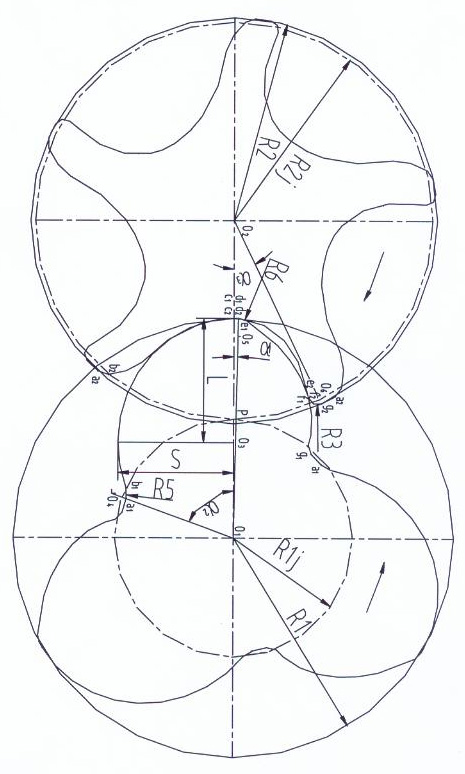
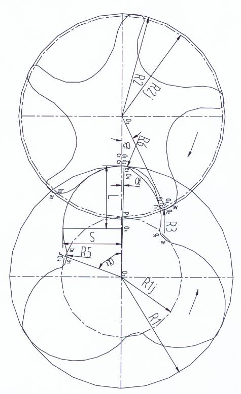
[0041] The construction of the twin-screw compressor rotor end profile of the present invention will be described in detail below in conjunction with the drawings and embodiments.

[0042] see figure 1 , The present invention provides a rotor profile of a twin-screw compressor. The profile below the center line in the figure is the profile of the active side, and the profile above the center line is the profile of the passive side.

[0043] The present invention adopts bilateral asymmetric molding lines, and the male and female rotor end surface molding lines are respectively composed of six sections of molding lines. The male and female rotor profile series of screw compressors are formed with the same center distance A and different sizes of female and male rotors. Among them, the molded line composition of the female rotor is as follows:

[0044] a 1 b 1 Segment: arc a 1 b 1 The dedendum circle of the front cut male rotor is at a 1 point, backcut ellipse arc b 1 c ...


PUM


Abstract

The invention relates to a twin-screw compressor rotor profile, wherein a two-side asymmetric profile is adopted, six sections of profiles are combined to form end face profiles of a female rotor and a male rotor, and the female rotor and the male rotor which are identical in central distance A and different in size are combined to a form a female / male rotor profile series of a screw compressor. An arc f2g2 with a certain radius and an arc envelope d2e2 at the addendum circle on the passive side of the female rotor end face profile are in smooth connection through taking a straight line e2f2 as a common tangent. The elliptic arc b1c1 on the male rotor end face profile is different from the ordinary arc pin tooth curve or the envelope and can enable the engagement and releasing of the male and female rotors to be more stable through properly adjusting the length ratio of the major and minor axes of the ellipse, so as to reduce noise and vibration. The included angle of the addendum arc c1d1 on the male rotor end face profile can be adjusted, and the addendum arc c1d1 is in tangent and smooth connection with both the elliptic arc b1c1 and an arc d1e1. The invention endows the rotors with the advantages of short contact line, small disclosed triangle, big flow passage area, streamlined rotor profile, reduced aerodynamic resistance and the like.

Description

technical field [0001] The invention relates to a screw compressor, in particular to a new screw rotor line suitable for a twin-screw compressor. Background technique [0002] The quality of the end surface profile of the screw compressor will directly affect the performance of the screw compressor, such as sealing, efficiency, and area utilization coefficient. At present, the popular profiles on the market include GHH profiles, Hitachi profiles, and SRM profiles, all of which have their own characteristics. [0003] Since the twin-screw compressor came out in the 1940s, it has developed rapidly and has been widely used in many fields. The update and development of the screw rotor profile is the main driving force for the development of twin-screw compressors. In the patent documents of various countries, screw rotor profiles emerge in endlessly, all for the purpose of improving efficiency and performance. The design of the screw rotor profile should usually consider the ...

Claims


Application Information

Patent Timeline
Patent Type & Authority Applications(China)
IPC IPC(8): F04C29/00F04C18/16
Inventor 张玉新刘琦董勇搏
Owner 南通永力液压设备有限公司
Why Eureka
Try Eureka