Inner chip removal deep hole drill

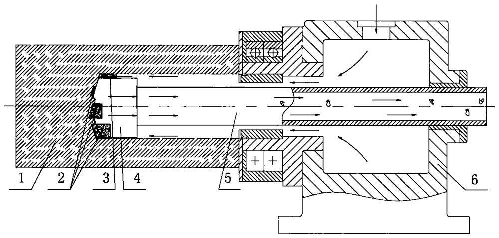
A technology for deep hole drilling and internal chip removal, which is applied in drilling/drilling equipment, drill repairing, drilling tool accessories, etc. It can solve problems such as tool structure asymmetry, tool deviation, workpiece deformation, etc., and achieve self-correction effect Good, high self-centering accuracy, short contact line effect

Pending Publication Date: 2021-03-09
ZHONGBEI UNIV
View PDF0 Cites 0 Cited by
  • Summary
  • Abstract
  • Description
  • Claims
  • Application Information

AI Technical Summary

Problems solved by technology

[0003] The traditional internal chip removal deep hole tool has the following disadvantages: First, the structure of the tool is asymmetrical, the resultant force of the cutting force acting on the workpiece is not zero, and the resultant force of the cutting force causes the workpiece to deform
Most deep hole parts have large length-to-diameter ratio and poor rigidity, so the actual processed deep holes have large errors in straightness and other shapes and positions
Second, there is no automatic deviation correction capability
When the deep hole tool is deflected due to factors such as uneven workpiece material and external interference, it is impossible to correct the deflection of the tool, and it is even more difficult to correct the deflection automatically
Third, the two guide strips located at the rear of the cutting edge are in close contact with the processed hole wall for guidance, but the wear and failure of the guide strips will affect the machining accuracy
The quality defect of the contact part between the guide bar and the hole wall can cause the tool to deviate

Method used


Image

  • Inner chip removal deep hole drill
  • Inner chip removal deep hole drill
  • Inner chip removal deep hole drill

Examples


Embodiment Construction

[0046] The implementation manners are further described below, and the specific implementation manners do not limit the present application in any way.

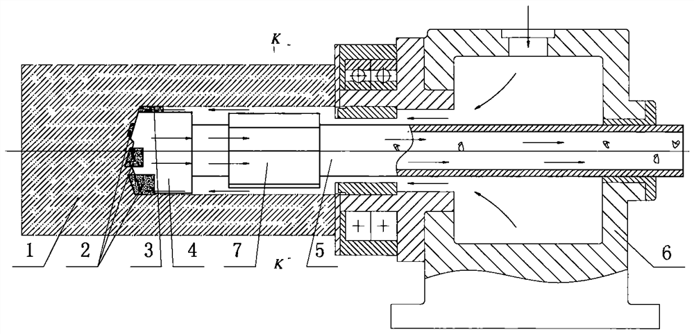
[0047] 1. The wedge-shaped part is a connecting structure or an integral structure.

[0048] 2. The force of the liquid is adjusted by mechanical, electrical or magnetic means.

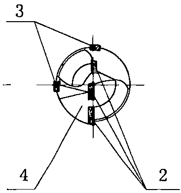
[0049] 3. The wedge-shaped contour of the wedge-shaped convex part is a circle, or an Archimedes spiral, or other curves.

[0050] 4. The blades are arranged symmetrically or asymmetrically; the liquid is oil or other liquid, which is filtered by a filter, centrifugal force, or magnetically.

[0051] 5. The wedge-shaped protrusion or the adjusting pad is in contact with the positioning piece.

[0052] 6. The material and heat treatment requirements of the top of the wedge-shaped protrusion are the same as or different from the material and heat treatment requirements of the main body of the wedge-shaped protrusion; the top of the wedge-shaped protr...


PUM


Abstract

The invention belongs to the field of deep hole machining, and particularly relates to an inner chip removal deep hole drill. The inner chip removal deep hole drill is provided with a blade, a cutterbody and a wedge-shaped part. Wedge-shaped protrusions are distributed on the wedge-shaped portion along the circumference, and the unilateral gap between the wedge-shaped protrusions and the inner wall of a deep hole is larger than or equal to 0 millimeter, when needed, the self-centering force of the deep hole drill can be precisely adjusted, the positions or postures of the wedge-shaped protrusions are changed through the positioning piece, a screw rod and a support, the thickness of a liquid film in a gap is changed, and therefore the acting force of liquid on the wedge-shaped outline is adjusted, the wedge-shaped contour curve of the wedge-shaped protruding part is a circle or an Archimedes spiral, the wedge-shaped part and the cutter body are of an integrated structure, or the wedge-shaped part is connected to the cutter body and a cutter bar through threads, and the tops of the wedge-shaped protrusions can be provided with coatings. According to the inner chip removal deep holedrill, larger liquid acting force can be obtained, a cutter system is high in precision, high-speed rotation can be achieved, installation and popularization are convenient, cutting fluid is clean, the deep hole drill can be used for deep hole or shallow hole machining and can be used for drilling or chambering, and the deep hole machining quality and efficiency are improved.

Description

technical field [0001] The invention belongs to the field of hole processing, and in particular relates to an internal chip removal deep hole drill. Background technique [0002] Deep hole processing tools are different from ordinary twist drills in structure. Deep hole tools include internal chip removal deep hole drills and external chip removal deep hole drills. figure 1 It is a front view schematic diagram of the machining principle of the existing internal chip removal deep hole tool. figure 2 is its side view diagram. Among the figure, 1 is a workpiece, 4 is a cutter body, which is a hollow structure, on which a cutting edge 2 and a guide bar 3 are fixed. 5 is a cutter bar (ie a drill pipe), and 6 is an oil feeder. The workpiece 1 rotates relative to the tool system. The oil used for cooling, lubricating and chip removal flows through the outside of the cutter bar 5, and the iron filings are discharged from the inner hole of the cutter bar. [0003] The tradition...

Claims


Application Information

Patent Timeline
Patent Type & Authority Applications(China)
IPC IPC(8): B23B51/00B23B47/34
CPCB23B47/34B23B51/00
Inventor 于大国杨志涌
Owner ZHONGBEI UNIV
Why Eureka
Try Eureka