
Core

A technology of movement and cover, applied in measuring devices, instruments, measuring fluid pressure, etc., can solve the problems of back and forth difference of instruments, tap displacement, central axis shaking, etc.

Active Publication Date: 2011-05-11
BEIJING BRIGHTY INSTR
View PDF0 Cites 0 Cited by
  • Summary
  • Abstract
  • Description
  • Claims
  • Application Information

AI Technical Summary

Problems solved by technology

[0007] Since the center shaft and the upper cover plate of the above-mentioned movement are clearance fit, the center shaft hole on the upper cover plate is directly processed. After a period of use, the center shaft hole often wears and becomes larger, and the center shaft shakes when it rotates. , There are problems such as back-and-forth difference and tapping displacement of the instrument, which seriously affect the test accuracy

Method used


Image

  • Core
  • Core
  • Core

Examples


Embodiment Construction

[0027] In order to make the above objects, features and advantages of the present invention more comprehensible, the embodiments of the present invention will be further described in detail below in conjunction with the accompanying drawings and specific implementation methods.

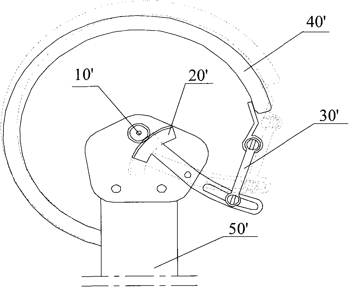
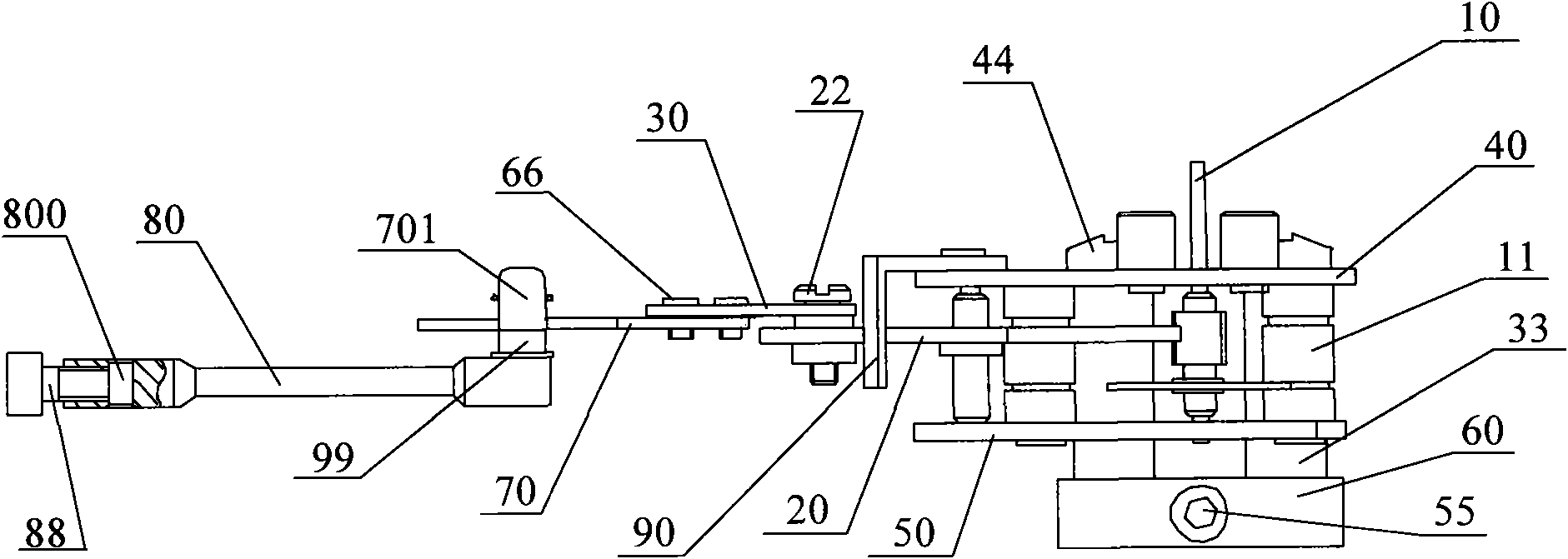
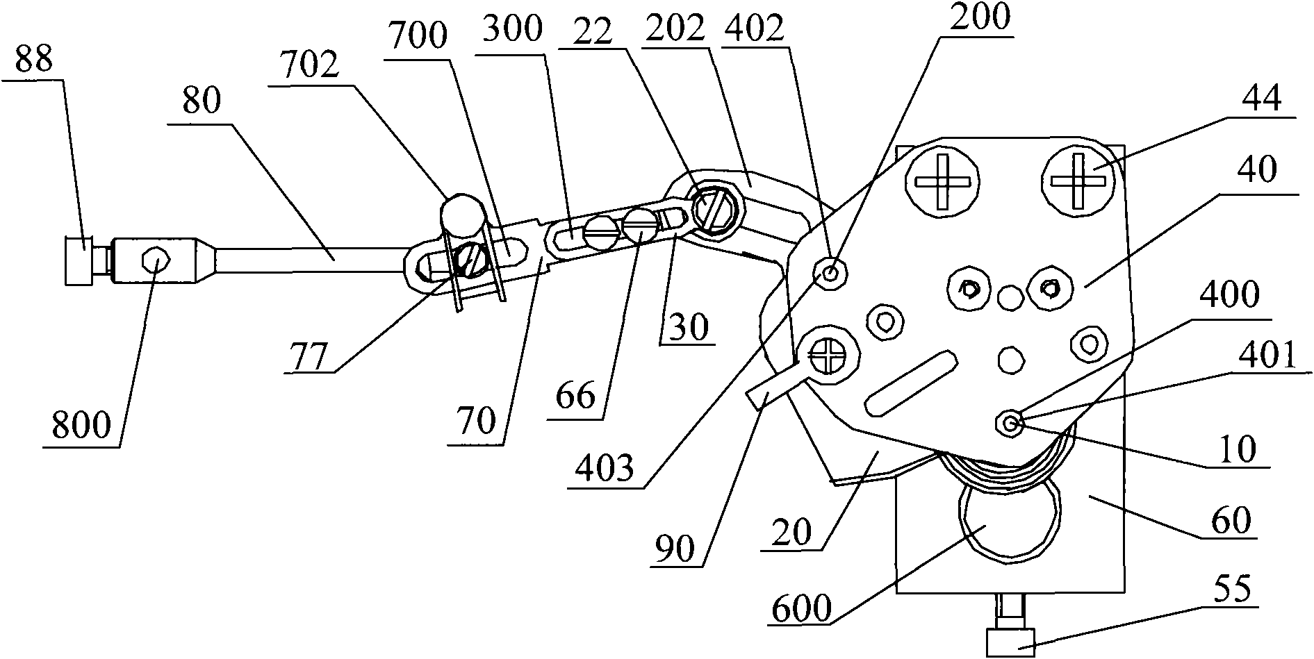
[0028] The invention provides a movement, please combine figure 2 , image 3 , the movement includes: the central axis 10, the fan teeth 20, the upper cover 40, the lower cover 50 and the connecting rod 30;

[0029] The upper cover plate 40 and the lower cover plate 50 clamp the central shaft 10 and the fan teeth 20, and the distance between the upper cover plate 40 and the lower cover plate 50 is fixed by at least two cylindrical movement bodies 11; the upper cover plate 40 The first bearing 401 is fixed in the first central axis hole 400 of the lower cover plate 50; 400 corresponds.

[0030] The upper end of the central shaft 10 passes through the first bearing 401 and cooperates with the inner ...


PUM


Abstract

The invention discloses a core which comprises a central shaft, a sector gear, an upper cover plate, a lower cover plate and a connecting rod, wherein the central shaft and the sector gear are clamped by the upper and the lower cover plates, the distance of the upper and the lower cover plates is constant through at least two cylindrical core bodies, a first bearing is fixed in a first central shaft hole of the upper cover plate, a second bearing is fixed in a second central shaft hole of the lower cover plate, the second central shaft hole corresponds to the first central shaft hole, the upper end of the central shaft passes through the first bearing and is matched with the inside pore diameter of the first bearing, and the lower end of the central shaft passes through the second bearing and is matched with the inside pore diameter of the second bearing. By arranging the bearings in the central shaft holes, the distance between the central shaft and the central shaft holes can keep relatively constant, so that the central shaft is rotated more stably and flexibly, the rotation accuracy of the core is improved, and the measurement accuracy of the gauge is improved.

Description

technical field [0001] The invention relates to the technical field of pressure measurement, in particular to a movement. Background technique [0002] Double-diaphragm high static pressure differential pressure gauge is a pressure gauge used to indicate the pressure difference ΔP. It is a special instrument that can withstand the maximum static pressure of 10Mpa on both sides and can indicate the differential pressure of ΔP=16KPa~2.5MPa. It is used in chemical industry, It is widely used in engineering projects such as gas pipelines, oil pipelines, pressurized pump stations, and nuclear power plants in machinery and petroleum industries. [0003] The movement (also known as the gear transmission mechanism of the pressure gauge) in the high static pressure differential pressure gauge is the core component, and its processing and manufacturing quality is directly related to the accuracy, service life and transmission stability of the differential pressure gauge. [0004] The...

Claims


Application Information

Patent Timeline
Patent Type & Authority Applications(China)
IPC IPC(8): G01L19/10G01L19/06
Inventor 白大成韩书华
Owner BEIJING BRIGHTY INSTR
Learn More