Electric control brake closing and breaking device

A technology for closing and opening the switch and controlling the switch, which is applied to the power device inside the switch, etc., can solve the problems of inconvenient installation and maintenance operations, difficulty in accurately realizing the closing and opening action, damage to the motor or clutch, etc., and achieve remote automatic switching. The effect of control, low noise and large output torque

Inactive Publication Date: 2011-05-11
张卫
View PDF6 Cites 3 Cited by
  • Summary
  • Abstract
  • Description
  • Claims
  • Application Information

AI Technical Summary

Problems solved by technology

The existing remote control closing and opening devices usually have complicated structures, such as outdoor dry-type high-voltage vacuum circuit breakers, and their closing and opening control devices usually include auxiliary switches, crank arms, screw rods, travel switches, rocker arms, interlocking devices, and drive shafts. And energy storage springs and other components, not only complex structure, high manufacturing cost, but also inconvenient to install, maintain and operate
[0003] At present, the existing electric closing and opening control devices generally use the motor to drive the main shaft to rotate through the mechanical clutch. At the moment of opening and closing, the energy stored in the energy storage spring will be transmitted to the motor through the mechanical clutch, which may sometimes cause the motor or the clutch to fail. damage
On the other hand, the existing electric closing and opening devices require experienced staff to adjust the closing and opening control nodes on site during installation, otherwise it may be difficult to accurately realize the closing and opening actions, and the assembly requirements are high

Method used


Image

  • Electric control brake closing and breaking device
  • Electric control brake closing and breaking device

Examples


Embodiment Construction

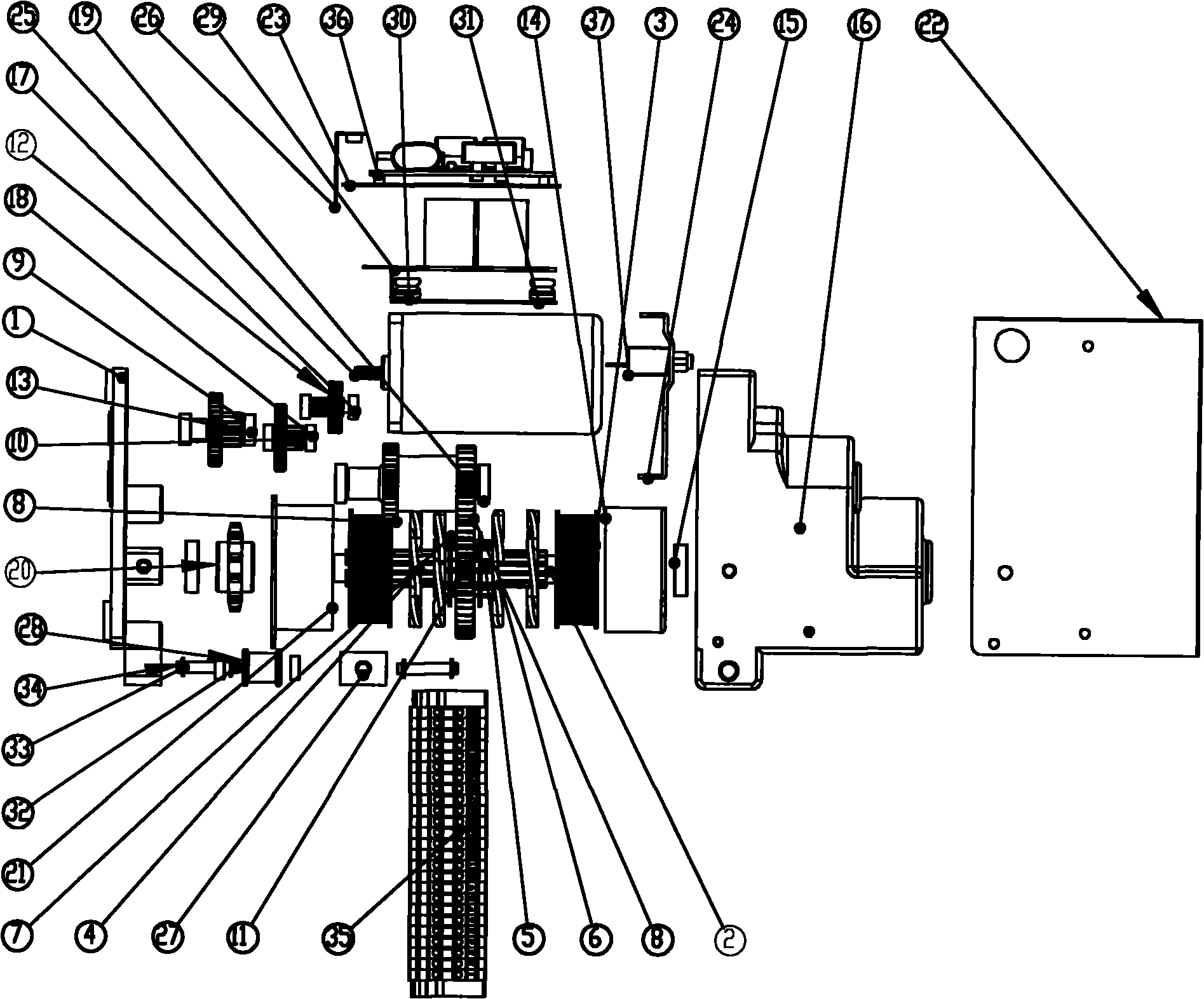
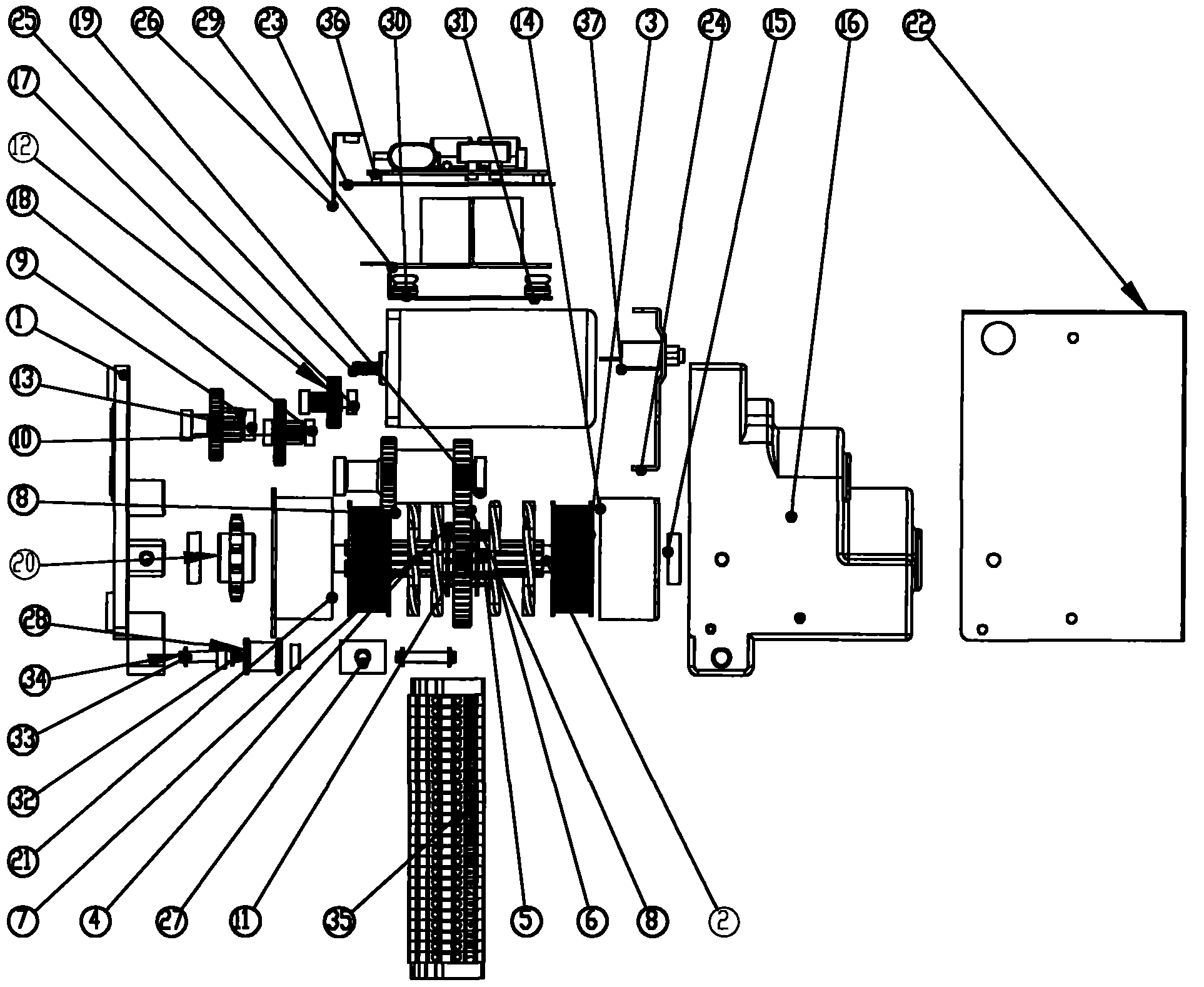
[0020] Such as figure 1 As shown, the electric control closing and opening device includes a housing 16, a motor 25, a control switch, a junction block 35, a transmission mechanism and a main shaft 2, and the motor 25 is connected to the main shaft 2 through a transmission transmission mechanism and outputs torque through the rotation of the main shaft 2. The speed change transmission mechanism includes a plurality of gear shafts connected in sequence, the motor is connected with the gears of the gear shafts through the gears provided on the main shaft, and the gears of the adjacent gear shafts are meshed with each other; the gear shafts are also connected with the electromagnetic clutch, Electromagnetic clutch is connected with main shaft 2; Described control switch is connected with motor 25 and electromagnetic clutch circuit respectively;

[0021] In this embodiment, the speed change transmission mechanism includes double pinion shafts 12, double pinion shafts A10, double p...


PUM


Abstract

The invention relates to an electric control brake closing and breaking device which comprises a casing, a motor, a variable-speed transmission mechanism and a main shaft, wherein the variable-speed transmission mechanism comprises a plurality of gear shafts which are connected sequentially, the motor is connected with the gear shafts through gears, the gear shafts are connected with an electromagnetic clutch, the electromagnetic clutch is connected with the main shaft, and the electromagnetic clutch can switch the rotation direction of the main shaft; the casing is provided with a circuit board, and the circuit board is connected with the casing through an antivibration pad and a vibration reduction bracket; and the motor is connected with a safety switch. According to the invention, theplurality of gear shafts and the electromagnetic clutch are adopted to form an overrun clutch, and the speed changing, the moment increasing and moment direction transferring are realized; and the motor is connected with the safety switch, and the circuit can be cut off automatically when the motor has an excessive load, thus the motor is protected. The electric control brake closing and breakingdevice has the advantages of simple structure, large output torque, low noise and no need of adjustment during the installation, is connected with the input shaft of a vacuum circuit breaker, is safeand reliable to use, is convenient to operate, and is favorable for realizing the long-distance automatic control of a high-voltage power grid.

Description

technical field [0001] The invention relates to a closing and opening control device, in particular to an electrically controlled closing and opening device for a high-voltage power grid circuit breaker. Background technique [0002] Existing high-voltage transmission and distribution grids generally require closing and opening control devices. For the safety of operators, the closing and opening control devices need to be far away from load switches or vacuum circuit breakers. The existing remote control closing and opening devices usually have complicated structures, such as outdoor dry-type high-voltage vacuum circuit breakers, and their closing and opening control devices usually include auxiliary switches, crank arms, screw rods, travel switches, rocker arms, interlocking devices, and drive shafts. Parts such as springs and energy storage springs are not only complicated in structure and high in manufacturing cost, but also inconvenient to install, maintain and operate....

Claims


Application Information

Patent Timeline
Patent Type & Authority Applications(China)
IPC IPC(8): H01H3/26
Inventor 张卫
Owner 张卫
Why Eureka
Try Eureka