Ion transporter, ion transport method, ion beam irradiator, and medical particle beam irradiator

An ion beam and conveyor technology, applied in radiation/particle processing, X-ray/γ-ray/particle irradiation therapy, discharge tube, etc., can solve the problem of reduced accuracy and difficulty in obtaining high-directional/high-intensity ion beam ions Beam Irradiator, Ion Beam 97 Focus Decreased, etc.

Inactive Publication Date: 2011-05-11
JAPAN ATOMIC ENERGY AGENCY INDEPENDANT ADMINISTRATIVE CORP +1
View PDF4 Cites 11 Cited by
  • Summary
  • Abstract
  • Description
  • Claims
  • Application Information

AI Technical Summary

Problems solved by technology

As a result, the following problems arise: the focusability of the ion beam 97 decreases, the intensity of the ion beam 97 at the output end becomes unstable, or the accuracy of the ion beam measurement at the output end is affected by the surface generated when the multipole magnet 98 is exposed to electrons. The voltage change caused by the generation of current reduces the
[0016] That is, it is difficult to obtain an ion beam irradiator capable of stably emitting a highly directional / high-intensity ion beam

Method used


Image

  • Ion transporter, ion transport method, ion beam irradiator, and medical particle beam irradiator
  • Ion transporter, ion transport method, ion beam irradiator, and medical particle beam irradiator
  • Ion transporter, ion transport method, ion beam irradiator, and medical particle beam irradiator

Examples


Embodiment Construction

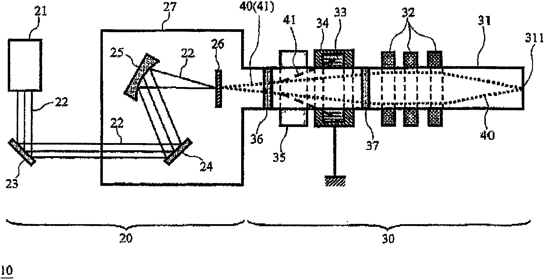
[0036] An ion beam irradiator according to one embodiment of the present invention will be described below. figure 1 is a view showing the configuration of the ion beam irradiator 10 . It is presumed that ion species constituting the ion beam (particle beam) generated by the ion beam irradiator 10 include protons. The ion beam irradiator 10 is composed of a combination of a laser-driven ion / electron generator (ion / electron generation source) 20 and an ion transporter 30, and is configured to direct the poorly directional ion beam emitted from the ion / electron generator 20 directed to the output while increasing the directionality of the ion beam or focusing the ion beam at the ion transporter 30 .

[0037] In the laser-driven ion beam irradiator 10 (ion / electron generator 20 ), high-intensity / ultrashort-pulse laser light 22 emitted from a laser source 21 enters a focusing mirror 25 through two plane mirrors 23 and 24 . The focus of the focusing mirror 25 is set on the targe...


PUM


Abstract

To obtain high-directivity, stable, and high-intensity ion beam. An ion beam irradiator 10 is constituted by a combination of a laser-driven ion / electron generator 20 and an ion transporter 30 and is configured to guide ion beam with low directivity emitted from the ion / electron generator 20 to the output end while increasing the directivity of the ion beam or focusing the ion beam at the ion transporter 30. In the ion transporter 30, an electron absorber 33 is provided around a beamline 31 at a location on the upstream side in terms of the flow of the ion beam relative to multipole magnets 32. The electron absorber 33 is formed of a material (e.g., polytetrafluoroethylene (PTFE)) that can effectively absorb high-energy electrons. The electron absorber 33 is surrounded by an X-ray shield 34 made of heavy metal such as lead.

Description

technical field [0001] The present invention relates to an ion transporter and an ion transport method capable of improving the directivity of an output particle beam (ion beam) when the particle beam passes. In addition, the present invention also relates to the structure of an ion beam irradiator and a medical particle beam irradiator using the ion transporter and ion transport method. Background technique [0002] Various techniques are known for manufacturing, thin film formation, analysis, medical practice, etc., by irradiating samples with ion beams obtained by accelerating ions including protons. In the technique, it is necessary to stably generate high-energy and high-intensity ion beams (particle beams). Generally, a device for generating and irradiating high-energy ion beams, particularly an accelerating device, requires large-scale equipment, thereby increasing the size of the entire device. Therefore, even though it is clear that such ion beam (particle beam) i...

Claims


Application Information

Patent Timeline
Patent Type & Authority Applications(China)
IPC IPC(8): H01J33/00H01J33/02A61N5/10
CPCA61N5/10A61N2005/1087A61N2005/1088A61N2005/1095G21K1/093
Inventor 榊泰直西内满美子堀利彦铃木将之井关康吉行健
Owner JAPAN ATOMIC ENERGY AGENCY INDEPENDANT ADMINISTRATIVE CORP
Why Eureka
Try Eureka