Excitation source for superconducting magnet and its operating method

A technology of superconducting magnet and excitation power supply, which is applied in the usage of superconducting elements, electrical components, emergency protection circuit devices, etc., can solve the problem of cutting off danger and achieve the effect of preventing damage

Inactive Publication Date: 2011-05-11
JAPAN SUPERCONDUCTOR TECH
View PDF6 Cites 4 Cited by
  • Summary
  • Abstract
  • Description
  • Claims
  • Application Information

AI Technical Summary

Problems solved by technology

However, when a huge current passes, it is dangerous to cut off (intercept) the interconnection (connection)

Method used


Image

  • Excitation source for superconducting magnet and its operating method
  • Excitation source for superconducting magnet and its operating method
  • Excitation source for superconducting magnet and its operating method

Examples


no. 1 Embodiment approach

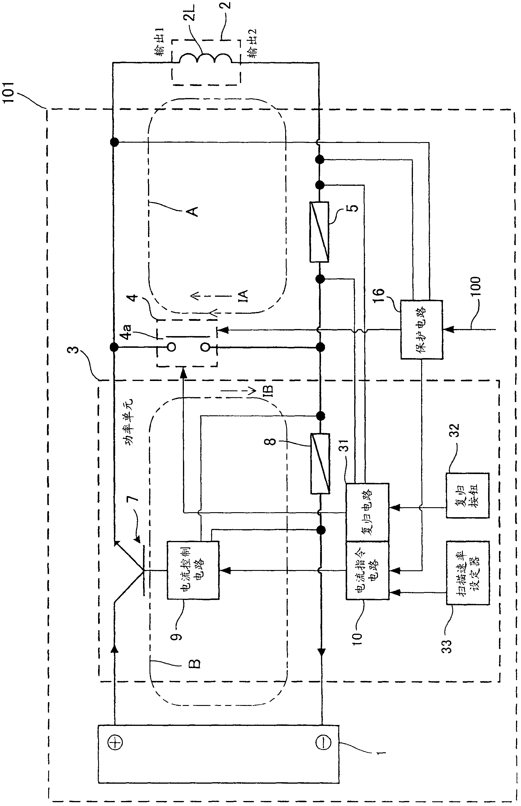
[0057] figure 1 It is a configuration diagram showing the field power supply 101 according to the first embodiment of the present invention.

[0058] (Structure of excitation power supply 101)

[0059] The excitation power source 101 is connected to the superconducting coil 2L, and is a power source for exciting the superconducting magnet 2 provided with the superconducting coil 2L. The superconducting coil 2L is wound by superconducting wire.

[0060] Such as figure 1 As shown, the excitation power supply 101 includes a power supply 1, a power unit 3, a first shunt resistor (first current detector), and a protection circuit 16 (protection device).

[0061] (power supply)

[0062] The power source 1 includes a transformer (not shown) connected to an AC power source, a smooth DC current rectified by the AC power of the transformer, and a transistor circuit (not shown) that supplies the superconducting coil 2L to the superconducting coil 2L. In addition, in the power supply 1, a commerc...

no. 2 Embodiment approach

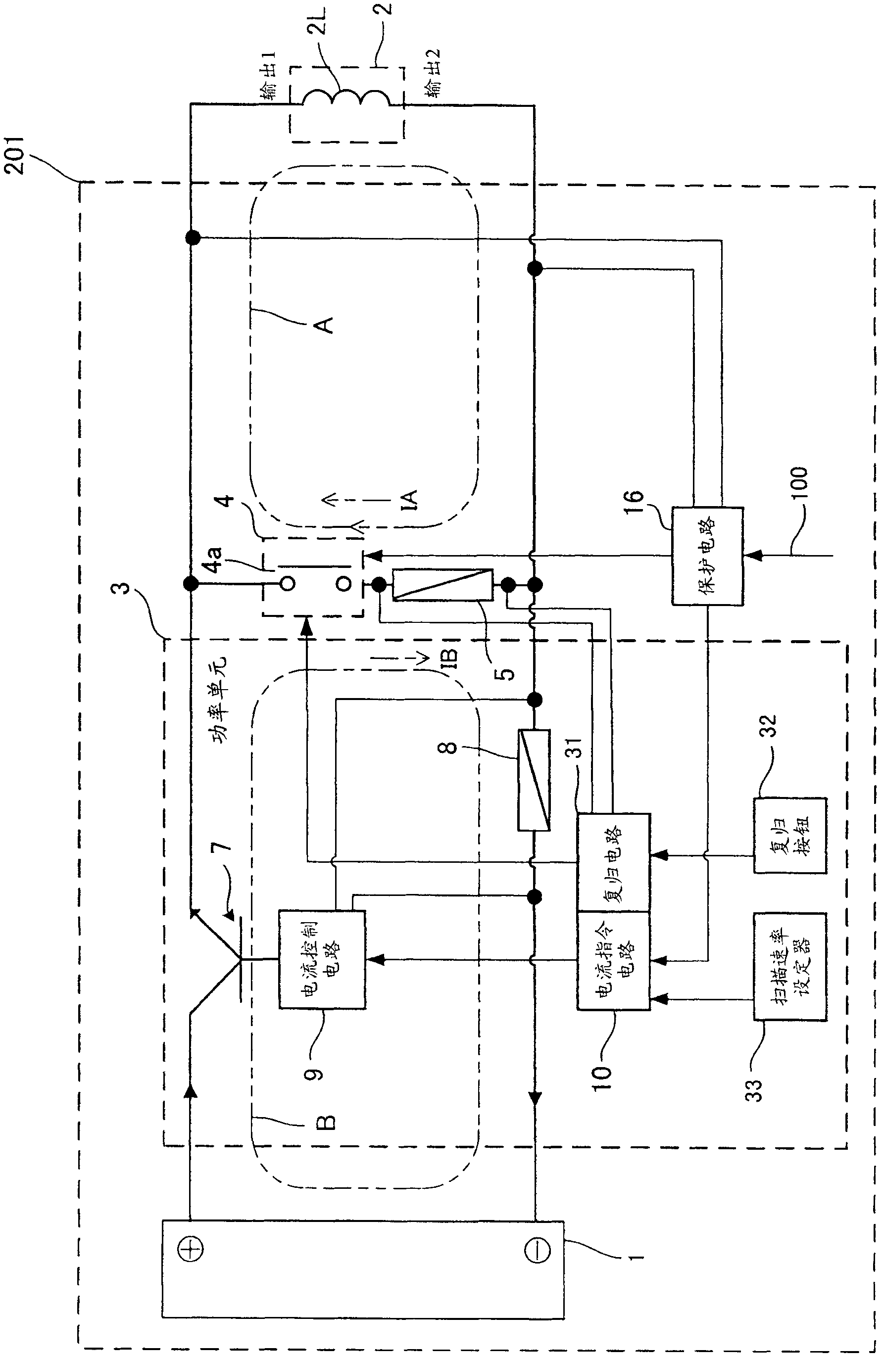
[0092] image 3 It is a configuration diagram showing an excitation power supply 201 according to the second embodiment of the present invention. The only difference from the first embodiment is the position of the first shunt resistor (first current detector). In this embodiment, the first shunt resistor 5 is provided at a position parallel to the superconducting coil 2L. In this way, the first shunt resistor 5 may be provided at a position capable of detecting the current IA passing through the superconducting coil 2L after the contact 4a of the protective relay is closed. In other words, the first shunt resistor 5 is set in series with the contact 4a, and is set at the output circuit B of the power unit 3 and the circuit A on the superconducting coil 2L side when the contact 4a is closed. Common part.

[0093] In this embodiment, the current control circuit 9 increases the output current value of the power cell 3 at a predetermined scan rate so that the detection value (curr...

no. 3 Embodiment approach

[0101] Figure 4 It is a configuration diagram showing an excitation power supply 301 according to the third embodiment of the present invention. The main difference between this embodiment and the first embodiment is that the excitation power supply 301 of this embodiment includes two (multiple) power units. In addition, the excitation power supply may be provided with three or more power units.

[0102] Such as Figure 4 As shown, the excitation power supply 301 includes a power supply 1, a first power unit 13, a second power unit 23, a first shunt resistor 5 (first current detector), a main control circuit 12 (main control device), and a distributor 14 ( Command distribution device), scan rate setter 33, protection circuit 16 (protection device), reset button 32, and reset circuit 131.

[0103] (First current detector)

[0104] The first shunt resistor 5 is a current detector that detects the output current value of the entire excitation power supply 301. In addition, the first...


PUM


Abstract

Provided is an excitation source for a superconducting magnet, which can quickly return to a normal state (a state of no short circuit) even when the two output ends of the excitation source undergo a short circuit, caused by abnormal situations like an incorrect quench detection, an internal abnormity and a sudden reduction in main power supply voltage, or when power is restored after being cut off. An excitation source (101) comprises a power supply (1), a power unit (3), a protective circuit (16) which will be closed to protect contacts (4a) undergoing short circuit at two output ends of the power unit (3) when an abnormality occurs, and a first shunt resistance (5) detecting the current value in a return circuit A, and a resetting circuit (31). After a protective relay (4) moves, closing the contact (4a) through the protective circuit (16), the resetting circuit (31) is reset from a protective state through disconnecting the contact (4a) by adopting the detection value of the first shunt resistance (5) and a second shunt resistance (8) and making the output current value of the power unit (3) and the current value passing through a superconducting coil (2L) being equal.

Description

Technical field [0001] The invention relates to an excitation power supply for superconducting magnets and an operation method thereof. Background technique [0002] In superconducting magnets, there is the so-called quench phenomenon, that is, the phenomenon that voltage is generated due to the destruction of the superconducting state and the zero resistance becomes the normal conductive state. In addition, the sudden change of the current due to the resistance is increasing. Superconducting magnets composed of superconducting coils will generate high voltage. In addition, on the contrary, if the current suddenly changes due to the problem of the excitation power supply itself, it will interact with the occurrence of the above-mentioned quench. On the excitation power supply side, the power element may be damaged due to the high voltage or the huge energy lost where it flows back. On the superconducting magnet side, quench occurs due to the sudden current change, so the superco...

Claims


Application Information

Patent Timeline
Patent Type & Authority Applications(China)
IPC IPC(8): H02H7/00
CPCY02E40/60
Inventor 永浜恭秀神门刚
Owner JAPAN SUPERCONDUCTOR TECH
Why Eureka
Try Eureka