Control circuit and method for buck-boost power supply converter

A technology of power converters and control circuits, applied in control/regulation systems, output power conversion devices, instruments, etc., can solve problems such as large output ripples, short working cycles, and discontinuous working cycles

Active Publication Date: 2011-05-11
RICHTEK TECH
View PDF5 Cites 19 Cited by
  • Summary
  • Abstract
  • Description
  • Claims
  • Application Information

AI Technical Summary

Problems solved by technology

In addition, when the signal VU rises or falls and approaches the peak value of the signal VX or the valley value of the signal VY, the duty cycle of the signal VB or VC will be very short, so the switch SWB or SWC may not be fully turned on (turn on) It turns off again, which serves no purpose other than increasing the switching loss
[0004] U.S. Patent No. 7,176,667 also proposes a control circuit for a buck-boost power converter, which uses a pulse width modulation s

Method used


Image

  • Control circuit and method for buck-boost power supply converter
  • Control circuit and method for buck-boost power supply converter
  • Control circuit and method for buck-boost power supply converter

Examples


Embodiment Construction

[0210] The present invention will be further described below in conjunction with embodiment and accompanying drawing.

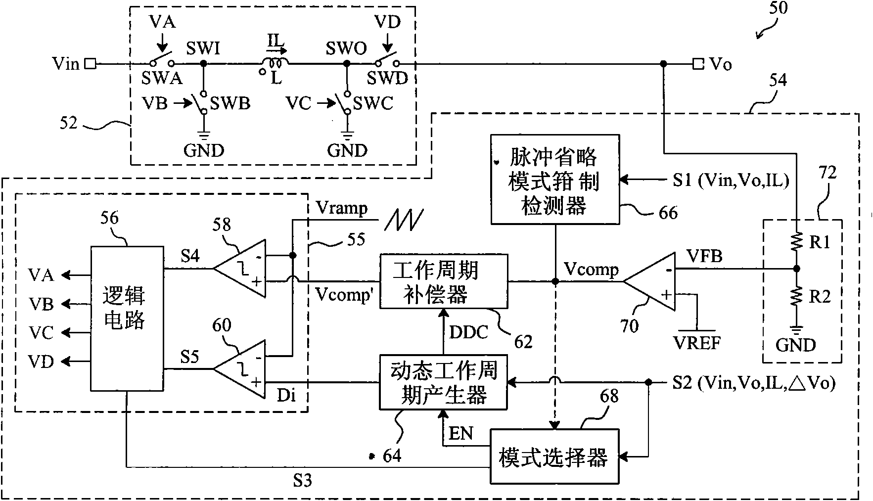
[0211] see now image 3 , image 3 A schematic diagram of an embodiment of the invention is shown. As shown in the figure, in the buck-boost power converter 50, the control circuit 54 provides control signals VA, VB, VC and VD to switch the switches SWA, SWB, and SWC and SWD are used to convert the input voltage Vin to the output voltage Vo. In the control circuit 54, the feedback circuit 72 detects the output voltage Vo to generate a feedback signal VFB, the error amplifier 70 amplifies the difference between the feedback signal VFB and the reference voltage VREF to generate an error signal Vcomp, and the pulse omission mode clamps the detector 66 clamps the level of the error signal Vcomp according to the detection signal S1, wherein the detection signal S1 is related to at least one of the input voltage Vin, the output voltage Vo and the inductor curren...


PUM


Abstract

The invention relates to a control circuit for a buck-boost power supply converter, which is used for providing a control signal to drive a buck-boost power level, so that input voltage is converted into output voltage, wherein the buck-boost power level comprises an inductor and at least two switches connected to the inductor. The control circuit is characterized by comprising a feedback circuit, an error amplifier, a dynamic work period generator and a driving circuit, wherein the feedback circuit detects the output voltage and generates a feedback signal; the error amplifier is connected with the feedback circuit and amplifies a difference value between the feedback signal and reference voltage to generate an error signal; the dynamic work period generator generates a first signal according to a detection signal after being started; and the driving circuit is connected with the error amplifier and the dynamic work period generator, and determines a control signal according to the error signal and the first signal. The control circuit and a control method for the buck-boost power supply converter have the advantages that: a switch witching order is optimized; the switching loss is reduced; the efficiency is improved; and output ripples are reduced.

Description

technical field [0001] The invention relates to a buck-boost power converter, in particular to a control circuit and method for a buck-boost power converter. Background technique [0002] figure 1 A known synchronous buck-boost power converter 10 is shown, which includes a buck-boost power stage 12 and a control circuit 22 that provides signals VA, VB, VC, and VD to switch switches SWA in the buck-boost power stage 12, respectively. , SWB, SWC and SWD to convert the input voltage Vin to the output voltage Vo. In the control circuit 14, the resistors R1 and R2 divide the output voltage Vo to generate the feedback signal VFB, and the error amplifier 24 amplifies the difference between the feedback signal VFB and the reference voltage Vref to generate the signal VCL to the signal generator 22, and the signal generator 22 provides signals VU, VX and VY, wherein the signal VU is related to the signal VCL, the signals VX and VY are sawtooth wave signals, the comparator 18 compar...

Claims


Application Information

Patent Timeline
IPC IPC(8): H02M3/158
Inventor 林水木
Owner RICHTEK TECH
Why Eureka
Try Eureka