Double reciprocation pump

A technology of reciprocating motion and movement, applied in the direction of pumps, piston pumps, pump components, etc., can solve the problems of unstable flow, increased liquid inertial resistance, unstable pump action, etc., and achieve the effect of suppressing pulsation and stabilizing pump action.

Active Publication Date: 2011-05-11
IWAKI
View PDF5 Cites 19 Cited by
  • Summary
  • Abstract
  • Description
  • Claims
  • Application Information

AI Technical Summary

Problems solved by technology

For example, when applied to semiconductors, there are problems such as: particles clogged in the filter are squeezed out by pulsation and mixed into the downstream side; or particles clogged in the filter leak from the joint due to shaking of the pipe ; or the liquid level of the cleaning tank fluctuates; or the front end of the nozzle used to spray the liquid on the wafer vibrates to reduce the cleaning efficiency; or the inertial resistance of the liquid increases to make the flow unstable
[0006] However, in the case of the double reciprocating pump disclosed in the above-mentioned Patent Document 1, at the end of the stroke of one pump chamber from the expansion process to the compression process, the expansion process of the other pump chamber starts, and the expansion process is performed by the contraction of the coil spring. Compensating for the delay in the start of the expansion process, compared with the method of actively repeating the process of ending and starting the compression process with a pair of pump chambers, there is a problem that the pulsation elimination effect is small
[0007] In addition, for the double reciprocating pump disclosed in Patent Document 2, the timing of switching between the expansion process and the compression process of the pump chamber is controlled by time, so the heat generation of the elastic member and the surrounding environment after the start of operation are controlled. When the number of strokes is changed over time, such as changes, there is a problem that the phase of the reciprocating motion gradually changes and the pump operation becomes unstable.

Method used


Image

  • Double reciprocation pump
  • Double reciprocation pump
  • Double reciprocation pump

Examples


no. 1 Embodiment approach

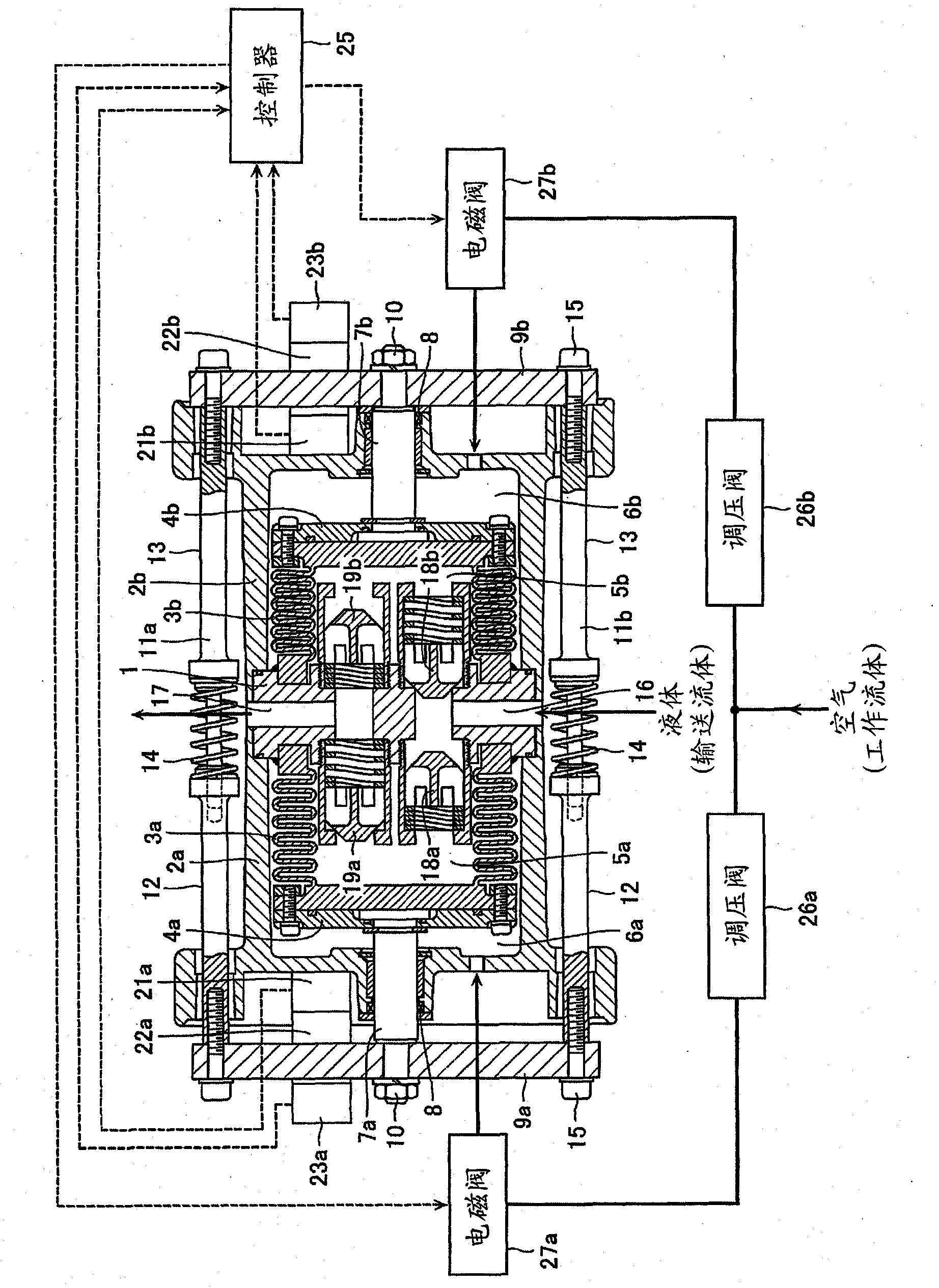
[0035] figure 1 It is a sectional view of a double reciprocating bellows pump according to the first embodiment of the present invention and a view showing its peripheral mechanism. Bottomed cylindrical air cylinders 2a, 2b serving as casing members are coaxially arranged on both sides of the pump head 1 arranged in the center, and a pair of spaces are formed inside the air cylinders 2a, 2b. Bottomed cylindrical bellows 3a, 3b are arranged coaxially in these spaces, respectively. Open ends of the bellows 3a, 3b are fixed to the pump head 1, and shaft fixing plates 4a, 4b are fixed to the bottoms of the bellows 3a, 3b. The inner side of the bellows 3a, 3b is used as the pump chamber 5a, 5b, and the outer side is used as the working chamber 6a, 6b, whereby the bellows 3a, 3b constitute a movable partition member for partitioning the internal space of the cylinder 2a, 2b.

[0036]One ends of shafts 7a, 7b extending coaxially are fixed to the shaft fixing plates 4a, 4b. The oth...

no. 2 Embodiment approach

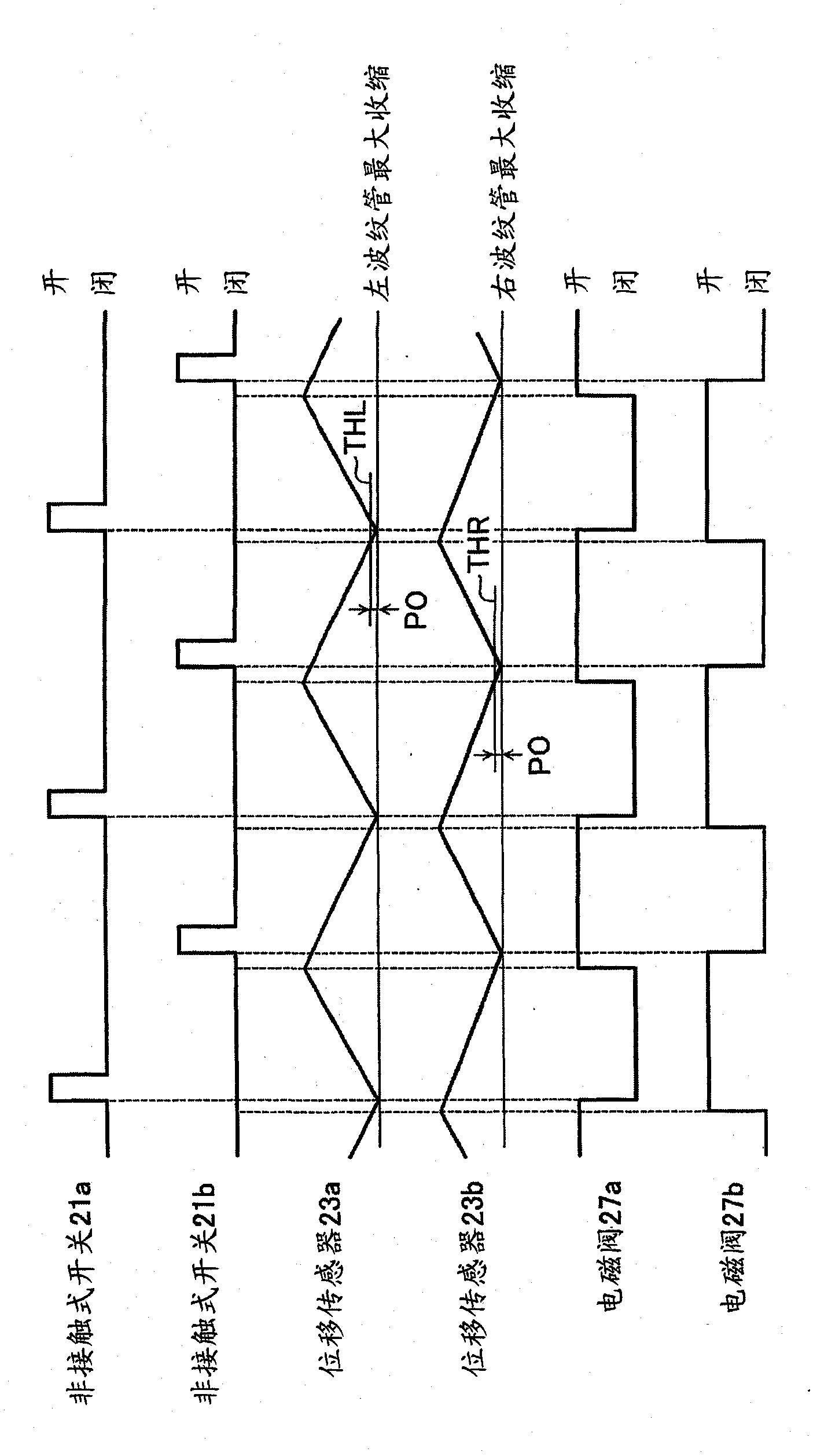
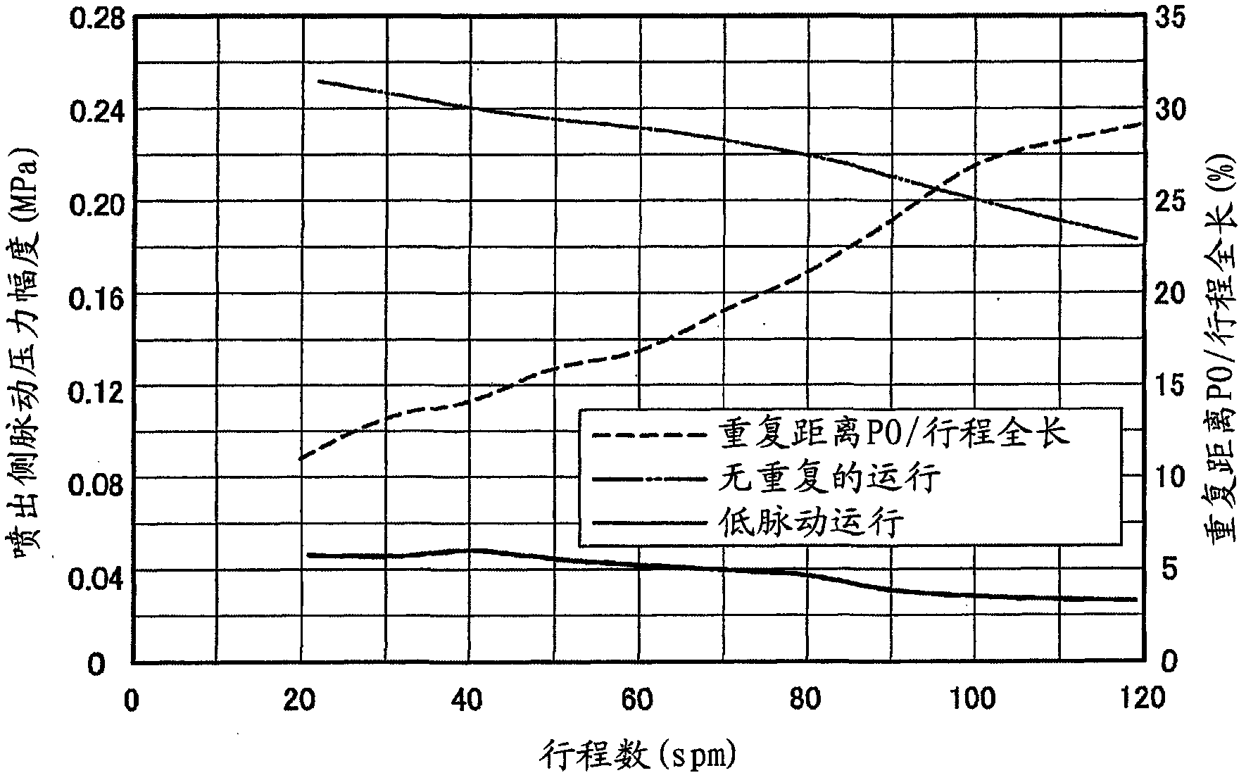
[0050] In the previous embodiments, it is not specifically mentioned that the repetition rate has a critical value, but if the repetition rate is too large, the force advancing one of the movable partition parts and the force advancing the other movable partition part will oppose and cause Pump action stops. Thus, the repetition rate at which pump action stops will be referred to hereinafter as the "critical repetition rate".

[0051] Figure 3B The critical repetition rate for each number of strokes under a certain condition is shown in . In order not to stop the operation of the pump, it is preferable to control the operation of the pump so as not to exceed the critical repetition rate, and to maintain the repetition rate within the range of pulsation reduction (pulsation elimination) indicated by the hatching in the figure. More preferably, the repetition rate is preferably maintained at a repetition rate that is several percent (eg, 1-3%) lower than the critical repetiti...

no. 3 Embodiment approach

[0058] Figure 4 It is a partial sectional view of the connecting shaft 31a (31b) used in the double reciprocating pump according to the third embodiment of the present invention.

[0059] In the first embodiment, the coil spring 14 is used as the telescopic member connecting the shafts 11a and 11b, but in this embodiment, an air shock absorber is used as the telescopic member. That is, the connection shaft 31a (31b) is comprised from the shaft part 32,33 and the air damper part 34 which connects them. The air damper portion 34 is composed of an air cylinder 35 attached to the end of the shaft portion 33 and a piston 36 attached to the end of the shaft portion 32 , and air of a predetermined pressure is supplied to the air cylinder 35 through the air inlet 37 .

[0060] According to the present embodiment, not only the optimal repetition rate but also the optimal elastic pressure (barne pressure) can be easily set. In addition, it is also possible to vary the elastic pressur...


PUM


Abstract

Disclosed is a double reciprocation pump wherein a pump operation is always stable, and pulsation is dampened. A pair of spaces are formed in the inside of a case member (2) in the axial direction of the case member (2). Each of movable partition members (3) is disposed so as be deformable in each of the pair of spaces in the axial direction of each space, so that each space is divided into a pump chamber (5) and an operation chamber (6) in the axial direction of each space. Coupling shafts (11) couple the movable partition members (3) via extendable members (14) so that the movable members (3) can extend in the axial direction thereof. Valve mechanisms (27) introduce a working fluid to the operation chambers (6), and discharge the working fluid from the operation chambers (6). A controller (25) switches the valve mechanisms (27) so that a distance of an overlapped portion in which a compression stroke of one pump chamber (5) and a compression stroke of the other pump chamber (5) are partially overlapped to each other, is formed, on the basis of the output of a displacement sensor (23) which continuously detects the displacement of each of the pair of movable partition members (3).

Description

technical field [0001] The present invention relates to a double-connected reciprocating pump. The double-connected reciprocating pump operates by repeating and alternately performing a compression process and an expansion process in a pair of pump chambers. The pair of pump chambers are connected by a connecting shaft. Formed by bellows, diaphragm, plunger and other movable partition parts, the present invention especially relates to a double reciprocating pump in which an elastic member is arranged on the connecting shaft to reduce the pulsation of the conveying fluid. Background technique [0002] There is known a duplex reciprocating pump as follows: a pair of closed spaces are divided into a pump chamber and a working chamber by means of a movable partition member such as a bellows connected by a connecting shaft, and a working fluid is alternately introduced into a pair of working chambers, thereby The connecting shaft is reciprocated to alternately compress and extend...

Claims


Application Information

Patent Timeline
IPC IPC(8): F04B9/129F04B9/137F04B43/06F04B49/00
CPCF04B9/137F04B53/003F04B43/086F04B43/113F04B53/10F04B53/16F05B2210/11Y10S417/00
Inventor 鬼塚敏树田边裕之岩渕恭平吉田笃史
Owner IWAKI
Why Eureka
Try Eureka