
Lower cavity and cavity of food rubbish treatment machine

A food waste treatment and cavity technology, applied in the direction of solid waste removal, etc., can solve the problems of drive motor stuck, drain blockage, poor effect, etc., to achieve the effect of reducing resistance, facilitating removal, and eliminating hindrance

Inactive Publication Date: 2011-05-18
万帝环境设备(郑州)有限公司
View PDF6 Cites 0 Cited by
  • Summary
  • Abstract
  • Description
  • Claims
  • Application Information

AI Technical Summary

Problems solved by technology

[0004] At present, the food waste processors on the market are not effective in treating food waste with long fibers. Food waste often slowly accumulates on one side of the drain, causing the entire drain to be blocked, and even the lower grinding chamber is filled and broken. Lock the drive motor

Method used


Image

  • Lower cavity and cavity of food rubbish treatment machine
  • Lower cavity and cavity of food rubbish treatment machine
  • Lower cavity and cavity of food rubbish treatment machine

Examples


Embodiment 1

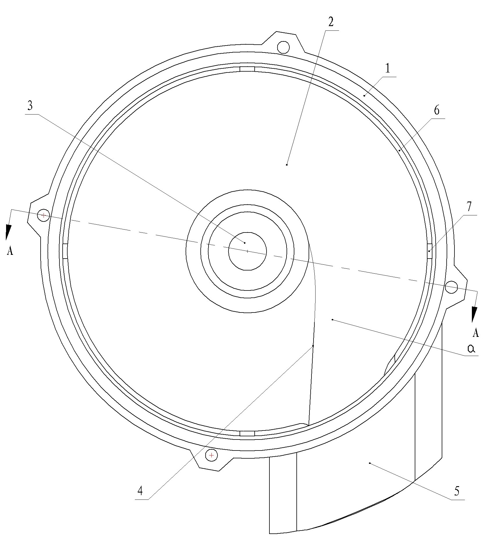
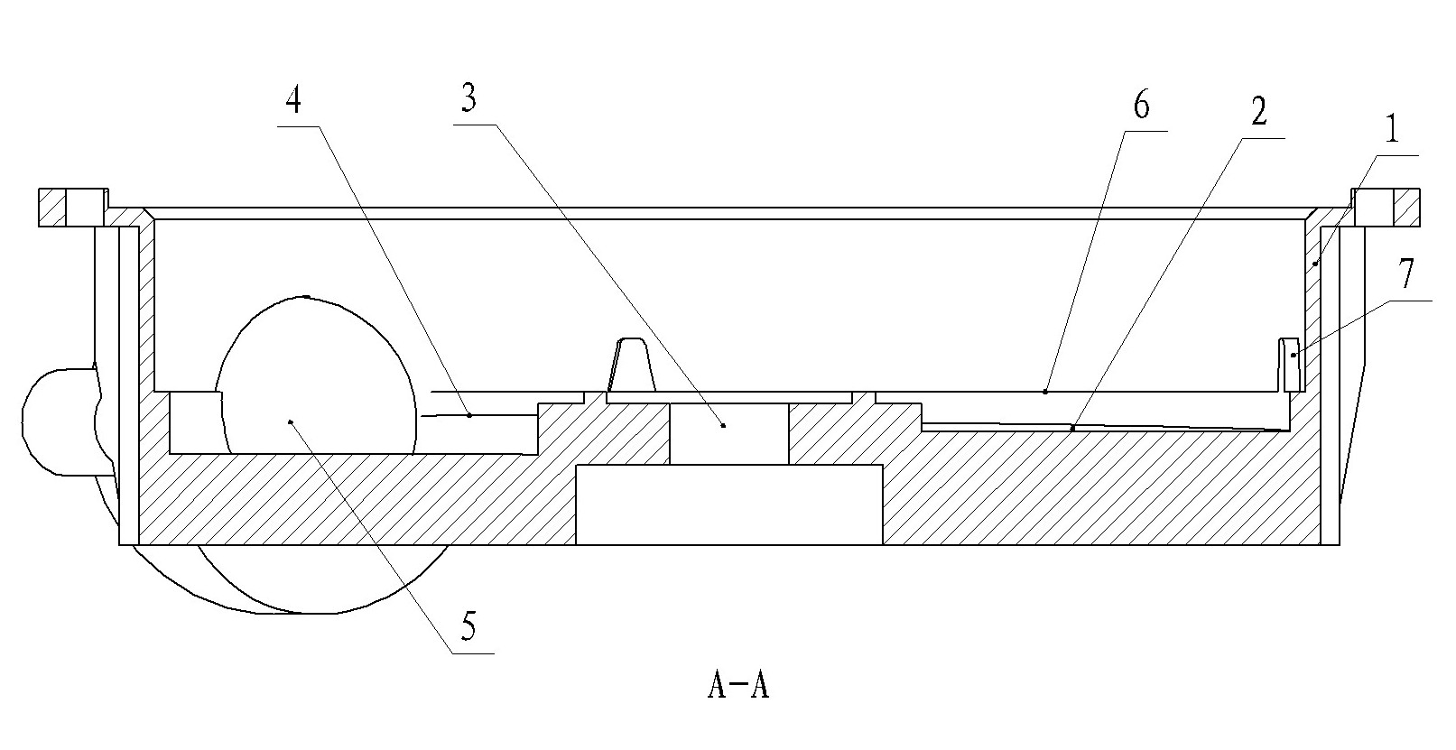
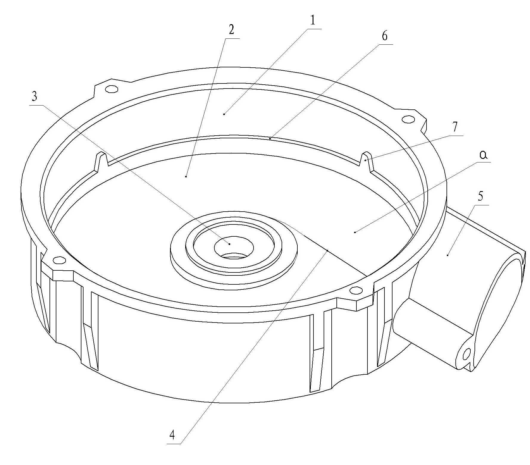
[0030] Embodiment one: see Figure 1-Figure 4 , the lower cavity of a food waste disposer in the figure, the lower cavity contains a cylindrical side wall and a lower circular bottom cover connected as one, the middle part of the bottom cover is provided with a shaft hole, and the side wall is provided with a discharge The inner surface of the discharge pipe is integrated with the bottom surface of the back cover through a transition connecting curved surface, and the axis of the discharge pipe is arranged in a direction approximately parallel to the tangential direction of the circumferential surface of the side wall.

[0031] The inner surface of the lower circular bottom cover is a helical surface, and the spiral descending direction matches the axial direction of the discharge pipe; The junction of the side walls.

[0032] The drop of the inner surface of the bottom cover near the discharge pipe is larger than the drop of the spiral surface.

[0033] A water-retaining co...

Embodiment 2

[0035] Embodiment two: see Figure 5 , Figure 6 ,as well as Figure 1-Figure 4 , a cavity of a food waste disposer in the figure includes an upper cavity and a lower cavity, and the upper and lower cavities are connected by fasteners and seals, and the lower cavity contains a cylindrical The side wall and the lower circular bottom cover, the middle part of the bottom cover is provided with a shaft hole, and the side wall is provided with a discharge pipe, the inner surface of the discharge pipe is connected with the bottom surface of the bottom cover through a transition connection surface, and the axis of the discharge pipe It is arranged in a direction approximately parallel to the tangential direction of the peripheral surface of the side wall.

[0036] The inner surface of the lower circular bottom cover is a helical surface, and the spiral descending direction matches the axial direction of the discharge pipe; The joint of the side wall; the drop of the inner surface ...


PUM


Abstract

The invention relates to a lower cavity and a cavity for a food rubbish treatment machine. The lower cavity comprises a cylindrical side wall and a lower round back cover which are connected into a whole, wherein the middle of the back cover is provided with a shaft hole; the side wall of the shaft hole is provided with a discharging pipe; the inner surface of the discharging pipe is connected with the bottom surface of the back cover into a whole through a transition curved surface; and the axis of the discharging pipe is arranged approximately parallel with the tangential direction of the side wall circumference surface. The cavity for the food rubbish treatment machine comprises an upper cavity and the lower cavity, wherein the upper and lower cavities are connected through a fastening piece and a sealing piece; the lower cavity comprises the cylindrical side wall and the lower round back cover which are connected into a whole; the middle of the back cover is provided with the shaft hole; the side wall of the shaft hole is provided with the discharging pipe; the inner surface of the discharging pipe is connected with the bottom surface of the back cover into a whole through the transition curved surface; and the axis of the discharging pipe is arranged approximately parallel with tangential direction of the side wall circumference surface. By the structure design of the lower cavity and the cavity, resistance is reduced, thereby avoiding blocking phenomenon.

Description

technical field [0001] The invention relates to the technical field of food waste disposal, in particular to a lower chamber and a chamber of a food waste disposal machine. [0002] Background technique [0003] The food waste disposer usually has a motor drive mechanism. When the food waste is crushed, it will be washed by water flow. The crushed waste will flow into the sewer along with the water flow, thus making perishable, such as bones, fruit shells, vegetable stems, tea leaves, etc. Food waste can be disposed of in a timely manner, reducing the use of plastic garbage bags and the work intensity of sanitation workers, bringing freshness and cleanliness to the family and community environment. [0004] At present, the food waste processors on the market are not effective in treating food waste with long fibers. Food waste often slowly accumulates on one side of the drain, causing the entire drain to be blocked, and even the lower grinding chamber is filled and broken. ...

Claims


Application Information

Patent Timeline
IPC IPC(8): B09B3/00
Inventor 王晨辉朱明扬
Owner 万帝环境设备(郑州)有限公司
Learn More