Compensating welding method of rake angle welding line of electron beam welding thin plate

A technology of electron beam welding and welding method, which is applied in the field of vacuum electron beam welding, can solve the problems that affect the welding quality, have undercuts, shrinkage grooves, and it is difficult to ensure the back molding, etc., so as to improve the welding quality, avoid incomplete penetration, Avoid the effect of surface undercut

Inactive Publication Date: 2011-05-18
SHENYANG AIRCRAFT CORP
View PDF3 Cites 2 Cited by
  • Summary
  • Abstract
  • Description
  • Claims
  • Application Information

AI Technical Summary

Problems solved by technology

[0002] At present, the voltage of the electron gun used for electron beam welding is 55KV, and the electron gun distance is 190 mm; the welding speed is 400mm / min, and the corresponding welding current is 22mA; the welding speed is 600mm / min, and the corresponding welding current is 29mA; the welding speed is 700mm / min, and the corresponding welding current 35mA; welding speed 1200mm / min, corresponding welding current 50mA; the thickness of the current thin-plate parts to be welded is 3mm, the butt joint angle is 14°-40.9°, and the welding seam forming width on the welding surface is required to be 4mm, and the welding seam forming width on the back of the penetration part is required The weld pool width is 1.5mm, and the width of the weld pool is 2mm; the electron beam welding with vertical incidence, because the electron beam weld pool is narrow, cannot accommodate the butt weld with a large oblique angle, and cannot meet the requirements of butt welding with a thin plate oblique angle, because the vertical The maximum oblique angle that can just be accommodated at the time of incidence is 14°, the thickness is 3mm, and the butt oblique angle is 14°-40.9°. The butt joint structure cannot be welded with vertical incidence electron beams; it is difficult to ensure the rear Forming, it is easy to cause welding defects such as incomplete welding or undercut, shrinkage groove, etc., which seriously affects the welding quality

Method used


Image

  • Compensating welding method of rake angle welding line of electron beam welding thin plate
  • Compensating welding method of rake angle welding line of electron beam welding thin plate
  • Compensating welding method of rake angle welding line of electron beam welding thin plate

Examples


Embodiment 1

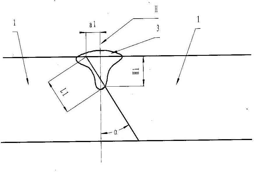
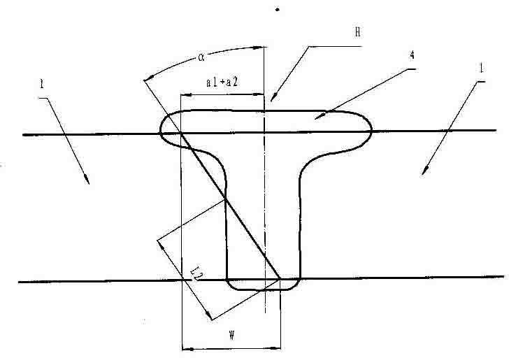
[0077] Example 1: The thickness of the part is 3mm, the butt joint angle of the oblique angle is 15.4°, the voltage of the electron gun is 55KV, and the distance between the electron gun is 190mm; the welding speed is 600mm / min, the welding current is 8mA, and the focusing current is 2.17-2.19A; take the positioning welding offset α1 =0.35 mm≤0.6 mm; for positioning welding, the surface weld width of the positioning welding is 1.5 mm, the stable minimum molten pool width is 0.6 mm, the stable penetration depth is 1 mm, and the end surface length of the oblique weld seam of the positioning welding is L1=1 / cos15.4° =1.037, such as Figure 4 shown.

[0078] Compensation welding: electron gun voltage 55KV, electron gun distance 190 mm; welding speed 700mm / min, welding current 35mA, focusing current 2.17A; offset α2=0.4 mm again on the basis of positioning welding offset, perform compensation welding, welding The thickness of the surface of the obtained weld is 3 mm, and the width...

Embodiment 1

[0103] 1.5 / L2=sin15.4°

[0104] L2=1.5 / sin15.4°=3.422

[0105] Part weld actual length

[0106] L=3 / cos15.4°=3.112

[0107] L1+L2=1.037+3.422=4.459>L=3.112

[0108] It can be seen from the above that through one offset compensation welding, the weld seam can make the weld seam of the 15.4° oblique angle butt joint parts completely merged.

Embodiment 2

[0109] Embodiment 2: The part thickness is 3mm, the butt joint angle of the oblique angle is 28.9°, the voltage of the electron gun is 55KV, and the distance between the electron gun is 190mm; the welding speed is 600mm / min, the welding current is 10mA, and the focusing current is 2.17-2.19A; take the positioning welding offset α1 =0.55 mm≤0.6 mm; for tack welding, the weld seam width on the tack welding surface is 1.5 mm, the minimum stable molten pool width is 0.6 mm, the stable penetration depth is 1 mm, and the molten pool includes the weld seam length L1=1 / cos28.9°=1.142 ,

[0110] Such as Figure 6 shown.

[0111] a1=0.55mm≤0.6mm

[0112] L1=1 / cos28.9°=1.142

[0113] Compensation welding: electron gun voltage 55KV, electron gun distance 190 mm; welding speed 600mm / min, welding current 29mA, focusing current 2.17A; offset α2=0.8 mm again on the basis of positioning welding offset, perform compensation welding, welding The formed thickness of the obtained weld surface ...


PUM

PropertyMeasurementUnit
thicknessaaaaaaaaaa

Abstract

The invention relates to a compensating welding method of a rake angle welding line of an electron beam welding thin plate, comprising the following steps of: (1) setting the thickness of a part as 3mm, a rake angle alpha as 14-40.9 degrees and electron beam welding in a butt joint structure; (2) determining the offset a1 of positioned welding: a half of the 1.2 mm width of a positioned welding molten pool is more than and equal to a1 or less than and equal to 0.6 mm; (3) carrying out the positioned welding; (4) determining the offset and the times of compensating welding; (5) carrying out first compensating welding; (6) carrying out second compensating welding; and (7) carrying out modifying welding. The invention is suitable for the butt joint welding of the rake angle of 14-40.9 degrees and prevents the incomplete fusion, surface undercut and ditch contraction, thereby enhancing the welding quality.

Description

technical field [0001] The invention is used for vacuum electron beam welding of oblique angle butt joint structures of thin plates. Background technique [0002] At present, the voltage of the electron gun used for electron beam welding is 55KV, and the electron gun distance is 190 mm; the welding speed is 400mm / min, and the corresponding welding current is 22mA; the welding speed is 600mm / min, and the corresponding welding current is 29mA; the welding speed is 700mm / min, and the corresponding welding current 35mA; welding speed 1200mm / min, corresponding welding current 50mA; the thickness of the current thin-plate parts to be welded is 3mm, the butt joint angle is 14°-40.9°, and the welding seam forming width on the welding surface is required to be 4mm, and the welding seam forming width on the back of the penetration part is required The weld pool width is 1.5mm, and the width of the weld pool is 2mm; the electron beam welding with vertical incidence, because the electro...

Claims


Application Information

Patent Timeline
Patent Type & Authority Applications(China)
IPC IPC(8): B23K15/00
Inventor 倪家强高峰
Owner SHENYANG AIRCRAFT CORP
Why Eureka
Try Eureka