Oil cylinder driving mechanism with buffer function for clamp

A technology of driving mechanism and oil cylinder, which is applied in the direction of clamping, manufacturing tools, metal processing machinery parts, etc., can solve the problems of poor stability and large impact of oil cylinder driving mechanism, achieve good stability and overcome the effect of end impact

Inactive Publication Date: 2011-05-18
DALIAN HUAGEN MACHINERY
View PDF6 Cites 4 Cited by
  • Summary
  • Abstract
  • Description
  • Claims
  • Application Information

AI Technical Summary

Problems solved by technology

The cylinder drive mechanism with this structure will have a large impact when the cylinder is close to the end of the stroke, and the stability is poor

Method used


Image

  • Oil cylinder driving mechanism with buffer function for clamp
  • Oil cylinder driving mechanism with buffer function for clamp
  • Oil cylinder driving mechanism with buffer function for clamp

Examples


Embodiment Construction

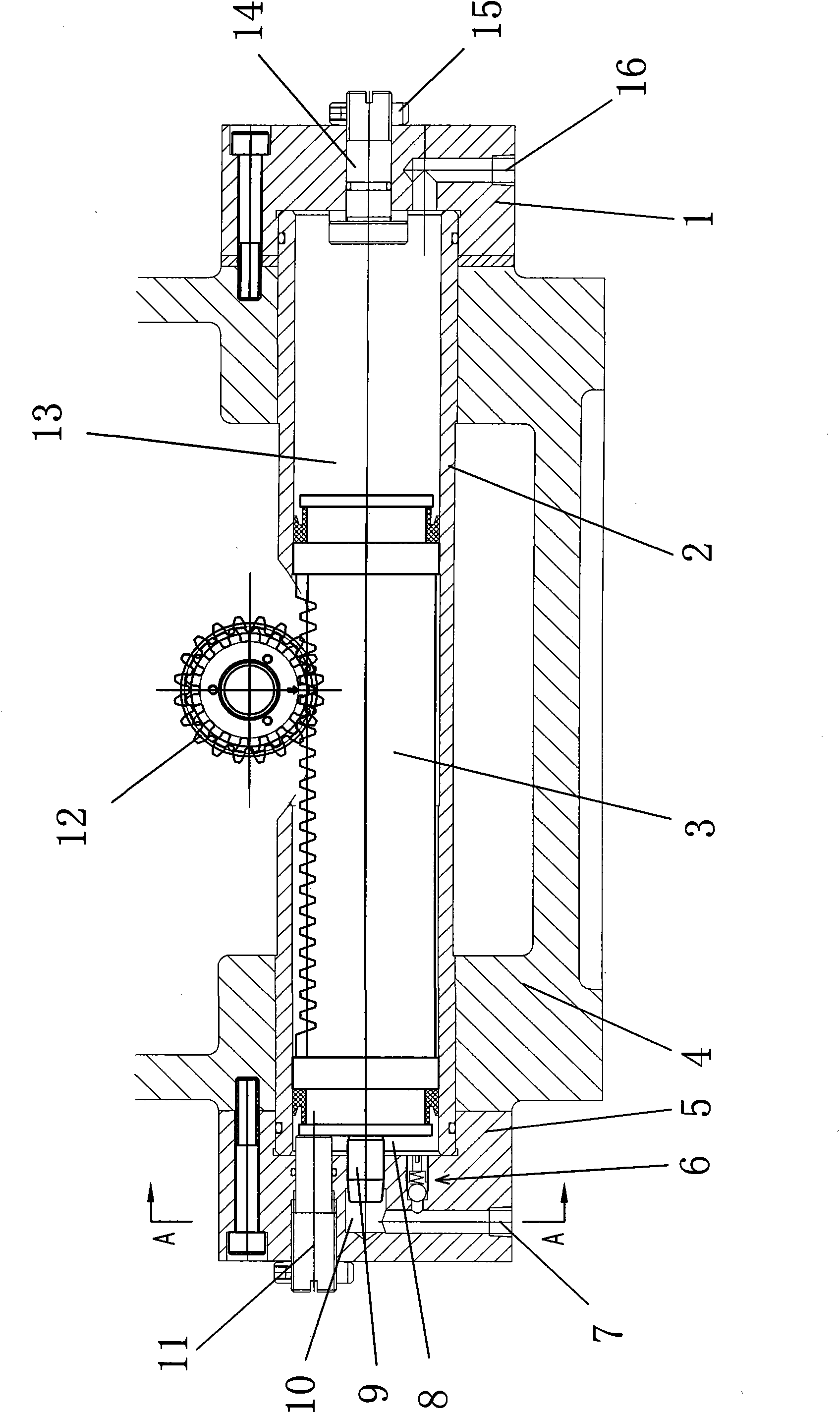
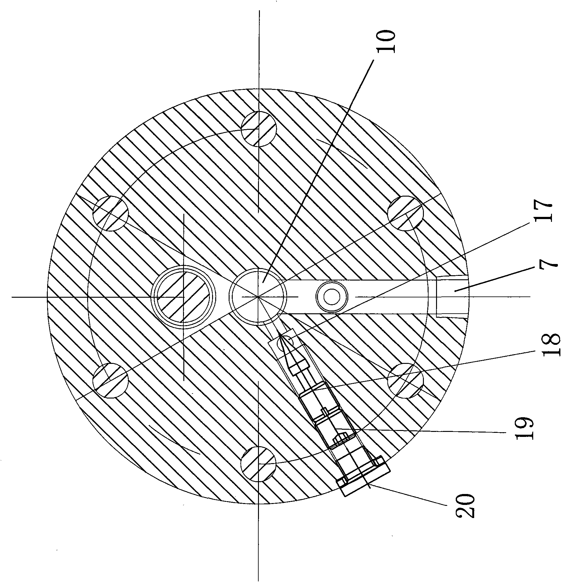
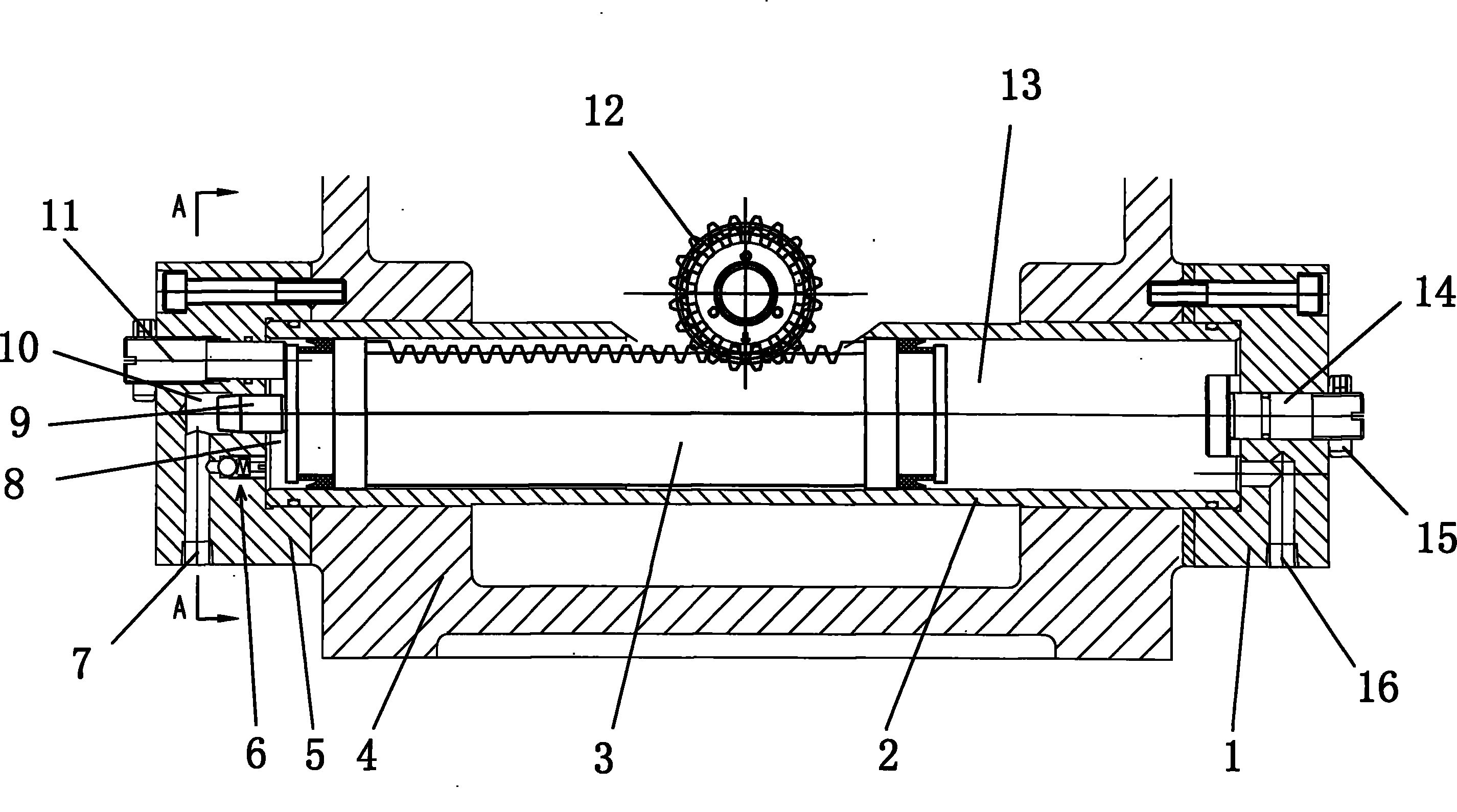
[0011] Such as figure 1 , 2 Shown: 4 is the clamp body, on which the clamp body 4 is fixed with an oil cylinder 2, the right end of the oil cylinder 2 has a right end cover 1, the right end cover 1 is fixedly connected with the clamp body 4 by bolts, and the center of the right end cover 1 is threaded. The right adjusting bolt 14 is fastened and positioned with a fastening nut 15 for setting the position of the right dead center of the piston. A right oil port 16 is processed on the right end cover 1 for connecting with the hydraulic control mechanism. The right end of the rack piston 3 matched with the oil cylinder 2 forms a right cavity 13 . The right cavity 13 communicates with the right oil port 16 .

[0012] The middle part of the rack piston 3 is exposed from the opening above the oil cylinder 2 and meshed with the gear 12. The rotating shaft of the gear 12 is connected with the fixture turntable to drive the turntable to rotate.

[0013] There is a left end cover 5 ...


PUM


Abstract

The invention discloses an oil cylinder driving mechanism with a buffer function for a clamp, comprising a clamp body, wherein an oil cylinder is arranged on the clamp body; a left end cover is arranged at one end of the oil cylinder; a right end cover is arranged at the other end of the oil cylinder; a left cavity is arranged at one end of a rack piston matched with the oil cylinder and is communicated with a left oil port on the left end cover; a right cavity is arranged at the other end of the rack piston and is communicated with a right oil port on the right end cover; a left end cover inner cavity is arranged on the inner side of the left end cover; the left end of the rack piston is connected with a plunger piston which is matched with the left end cover inner cavity; the left cavity is communicated with the left oil port through the left end cover inner cavity; a one-way valve is arranged between the left oil port and the left cavity on the left end cover; a valve core hole is formed in the left end cover by processing; a valve core is connected with an internal thread of the valve core hole; a communicating hole is formed in the left end cover by processing and is communicated with the left cavity, the valve core hole and the left end cover inner cavity; the internal thread of the valve core hole is connected with a fastening bolt; and a screed plug with a sealing ringis arranged at the port of the valve core hole. The rack piston is buffered when approaching to the left end in the work process and the phenomenon that the tail end is impacted is overcome; and the oil cylinder driving mechanism has better stable performance.

Description

technical field [0001] The invention relates to an oil cylinder driving mechanism, in particular to an oil cylinder driving mechanism with a buffer function used on a fixture. Background technique [0002] At present, the rotation of the turntable surface of the horizontal machining center is completed by the oil cylinder drive mechanism. There are four stop positions on the turntable surface for clamping the workpiece with the fixture. At present, the structure of this oil cylinder drive mechanism is that an oil cylinder is fixed on the clamp body, one end of the oil cylinder has a left end cover, the other end has a right end cover, and one end of the rack piston matched with the oil cylinder has a left cavity and is connected with the left oil on the left end cover. The other end of the rack piston has a right cavity and communicates with the right oil port on the right end cover; the middle part of the rack piston is exposed from the opening on the oil cylinder and meshe...

Claims


Application Information

Patent Timeline
Patent Type & Authority Applications(China)
IPC IPC(8): B23Q3/00B23Q5/00
Inventor 刘广永于俊光刘卫巍
Owner DALIAN HUAGEN MACHINERY
Why Eureka
Try Eureka